RL78/G10 CHAPTER 15 KEY INTERRUPT FUNCTION
R01UH0384EJ0311 Rev. 3.11 520
Dec 22, 2016
15.3.3 Key return flag register (KRF)
This register controls the key interrupt flags (KRF0 to KRF5).
The KRF register can be set by a 1-bit or 8-bit memory manipulation instruction.
Reset signal generation clears this register to 00H.
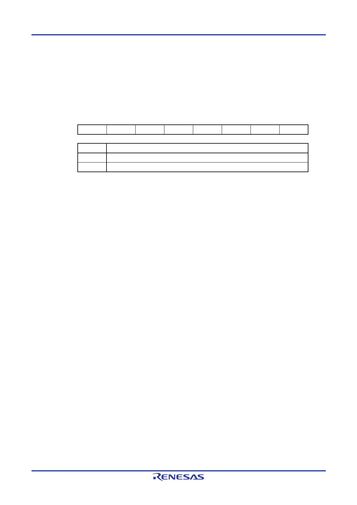
Figure 15-4. Format of Key Return Flag Register (KRF)
ddress: FFF35H After reset: 00H R/W
Note
Symbol 7 6 5 4 3 2 1 0
KRF 0 0 KRF5 KRF4 KRF3 KRF2 KRF1 KRF0
KRFn Key interrupt flag
0 No key interrupt signal has been detected.
1 A key interrupt signal has been detected.
Note Writing to 1 is invalid. To clear KRFn, write “0” to the target bits and write “1” to other bits,
with the 8-bit memory manipulation instruction.
Caution When the key interrupt flag is not used (KRMD = 0), accessing the KRF register is
prohibited.
15.3.4 Registers controlling port functions of key interrupt input pins
Using a port pin for key interrupt input requires setting of the registers that control the port functions multiplexed on the
target pin (port mode registers 0, 4 (PM0, PM4) and port mode control register 0 (PMC0)).
For details, see 4.3.1 Port mode registers 0, 4 (PM0, PM4) and 4.3.5 Port mode control register 0 (PMC0).
For an example of settings when using a port for key interrupt input, see 4.5.3 Example of register settings for port
and alternate functions used.
Using a port pin with a multiplexed key interrupt input function (e.g. P01/ANI0/SI00/RXD0/SDA00/KR2)
for key interrupt input requires setting the corresponding bit in the port mode register 0 (PM0) to 1, and the
corresponding bit in the pot mode control register 0 (PMC0) to 0. In this case, the corresponding bit in the port register 0
(P0) can be set to 0 or 1.
Example: When P01/ANI0/SI00/RXD0/SDA00/KR2 is to be used for key interrupt input
Set the PMC01 bit of port mode control register 0 to 0.
Set the PM01 bit of port mode register 0 to 1.

 Loading...


