RL78/G10 CHAPTER 4 PORT FUNCTIONS
R01UH0384EJ0311 Rev. 3.11 62
Dec 22, 2016
4.3.2 Port registers 0, 4, 12, 13 (P0, P4, P12, P13)
These registers set the output latch value of a port.
If the data is read in the input mode, the pin level is read. If it is read in the output mode, the output latch value is
read
Note
.
These registers can be set by a 1-bit or 8-bit memory manipulation instruction.
Reset signal generation sets the P12 and P13 registers to the undefined value, and clears the other registers to 00H.
Note When a pin that is set as an analog input pin (PMC0x = 1, PM0x = 1) is read, the value read is always 0
regardless of the input signal level on the pin.
When the data bit for P125 is read while the setting for the P125/KR1/RESET pin is RESET input (PORTSELB
= 1), the value read is always 1.
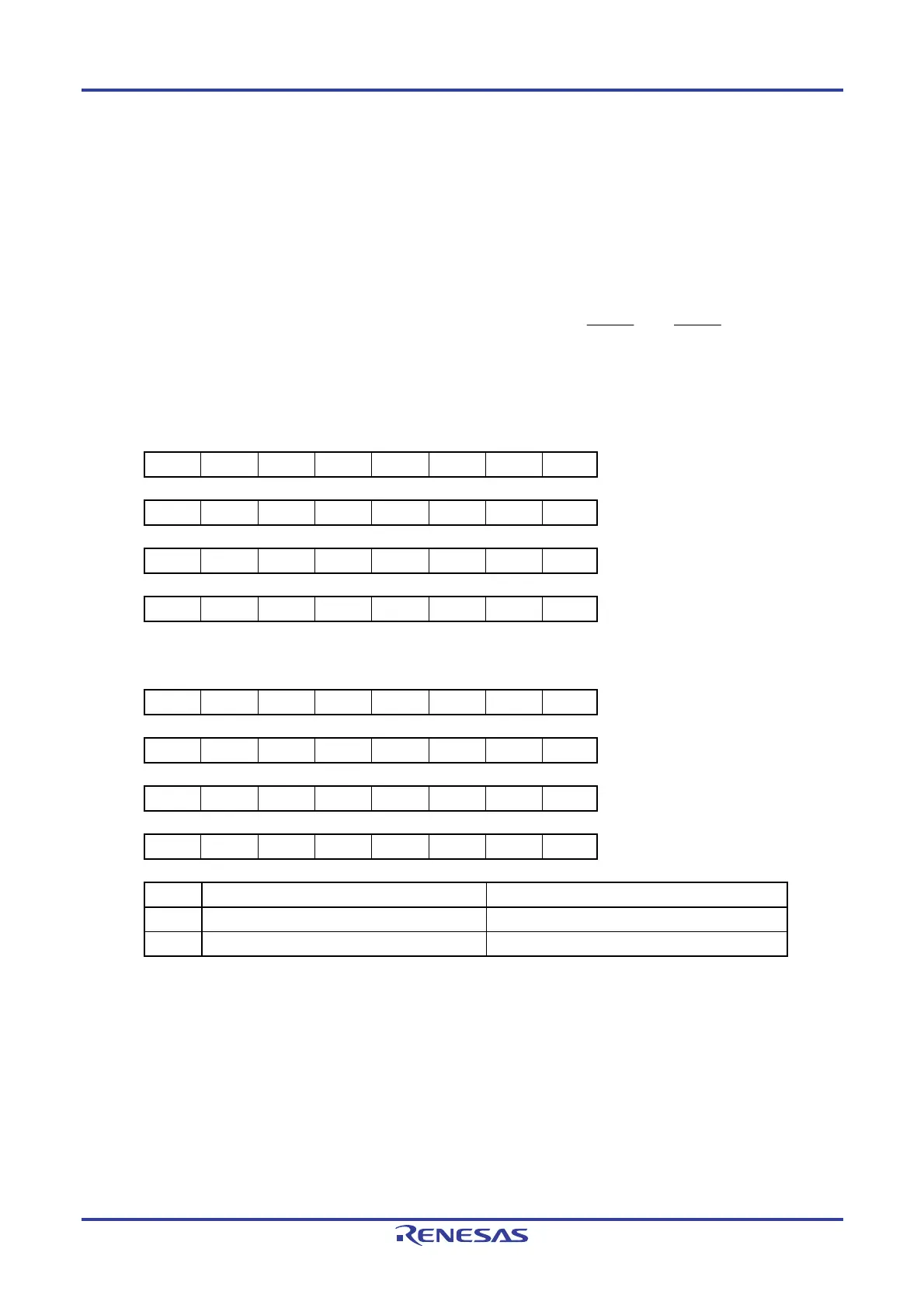
Figure 4-2. Format of Port Registers 0, 4, 12, 13 (P0, P4, P12, P13)
10-pin products
Symbol 7 6 5 4 3 2 1 0 Address After reset R/W
P0 0 0 0 P04 P03 P02 P01 P00 FFF00H 00H (output latch) R/W
P4 0 0 0 0 0 0 0 P40 FFF04H 00H (output latch) R/W
P12 0 0 P125 0 0 0 0 0 FFF0CH Undefined R
P13 P137 0 0 0 0 0 0 0 FFF0DH Undefined R
16-pin products
Symbol 7 6 5 4 3 2 1 0 Address After reset R/W
P0 P07 P06 P05 P04 P03 P02 P01 P00 FFF00H 00H (output latch) R/W
P4 0 0 0 0 0 0 P41 P40 FFF04H 00H (output latch) R/W
P12 0 0 P125 0 0 P122 P121 0 FFF0CH Undefined R
P13 P137 0 0 0 0 0 0 0 FFF0DH Undefined R
Pmn Output data control (in output mode) Input data read (in input mode)
0 Output 0 Input low level
1 Output 1 Input high level
m = 0, 4, 12, 13; n = 0 to 7
Caution Be sure to set bits that are not mounted to their initial values.

 Loading...


