RL78/G10 CHAPTER 12 SERIAL ARRAY UNIT
R01UH0384EJ0311 Rev. 3.11 295
Dec 22, 2016
12.3.10 Serial channel enable status register 0 (SE0)
The SE0 register indicates whether the data transmission/reception operation of each channel is enabled or disabled.
When 1 is written to a bit of serial channel start register 0 (SS0), the corresponding bit of this register is set to 1. When
1 is written to a bit of serial channel stop register 0 (ST0), the corresponding bit of this register is cleared to 0.
If the operation of channel n is enabled, the value of the CKO0n bit (serial clock output of channel n) of serial output
register 0 (SO0) cannot be rewritten by software, and a value is output from the serial clock pin according to the
communication operation.
If the operation of channel n is disabled, the value of the CKO0n bit of the SO0 register can be set by software and its
value is output from the serial clock pin. In this way, any waveform, such as that of a start condition/stop condition, can be
created by software.
The SE0 register can be read by a 1-bit or 8-bit memory manipulation instruction.
Reset signal generation clears the SE0 register to 00H.
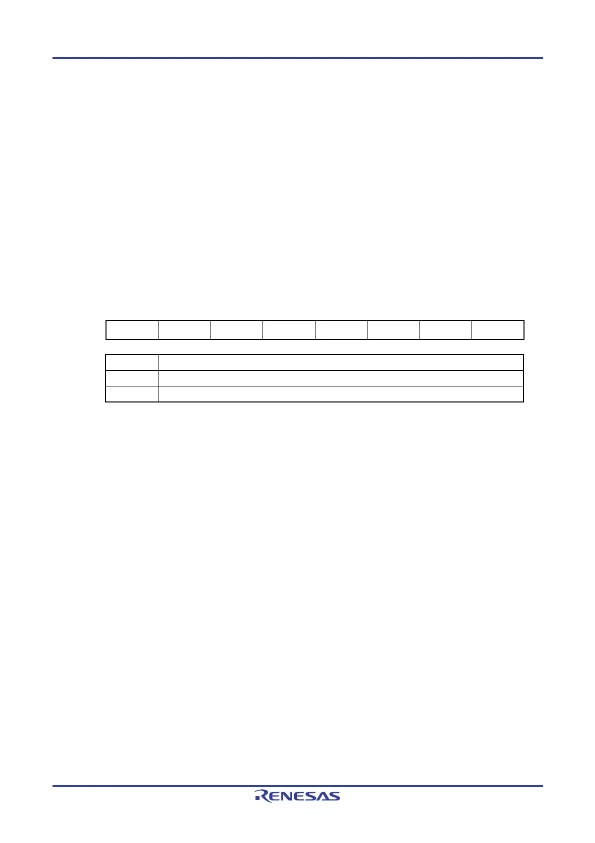
Figure 12-12. Format of Serial Channel Enable Status Register 0 (SE0)
Address: F0120H (SE0) After reset: 00H R
Symbol
7 6 5 4 3 2 1 0
SE0 0 0 0 0 0 0 SE01 SE00
SE0n Indication of operation enable/disable status of channel n
0 Operation is disabled (stopped)
1 Operation is enabled.
Caution Be sure to clear bits 2 to 7 to 0.
Remark n: Channel number (n = 0, 1)

 Loading...


