RL78/G10 CHAPTER 6 TIMER ARRAY UNIT
R01UH0384EJ0311 Rev. 3.11 146
Dec 22, 2016
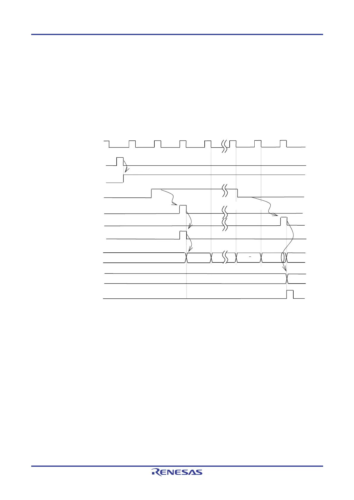
(5) Capture & one-count mode operation (high-level width is measured)
<1> Operation is enabled (TE0n = 1) by writing 1 to the TS0n bit of timer channel start register 0 (TS0).
<2> Timer count register 0n (TCR0n) holds the initial value until start trigger generation.
<3> Rising edge of the TI0n input is detected.
<4> On start trigger detection, the value of 0000H is loaded to the TCR0n register and count starts.
<5> On detection of the falling edge of the TI0n input, the value of the TCR0n register is captured to timer data
register 0n (TDR0n) and the interrupt request signal (INTTM0n) is generated.
Figure 6-28. Operation Timing (In Capture & One-count Mode: High-level Width Measurement)
f
MC
(f
TCLK
)
TS0n(Write)
TE0n
TI0n input
<1>
<2>
Rising edge
Edge detection
<4>
TCR0n
Initial value
m 1
m
TDR0n
Start trigger
detection signal
<3>
Falling edge
0000
m
Edge detection
0000
m+1
INTTM0n
<5>
Remark Figure 6-28 shows the timing when the noise filter is not used. When the noise filter is on-state, the edge
detection is delayed by two cycles of the operating clock (f
MCK) from the TI0n input (totally 3 to 4 cycles).
The error of one cycle is due to the asynchronous timing between the TI0n input and operating clock
(f
MCK).

 Loading...


