RL78/G10 CHAPTER 12 SERIAL ARRAY UNIT
R01UH0384EJ0311 Rev. 3.11 288
Dec 22, 2016
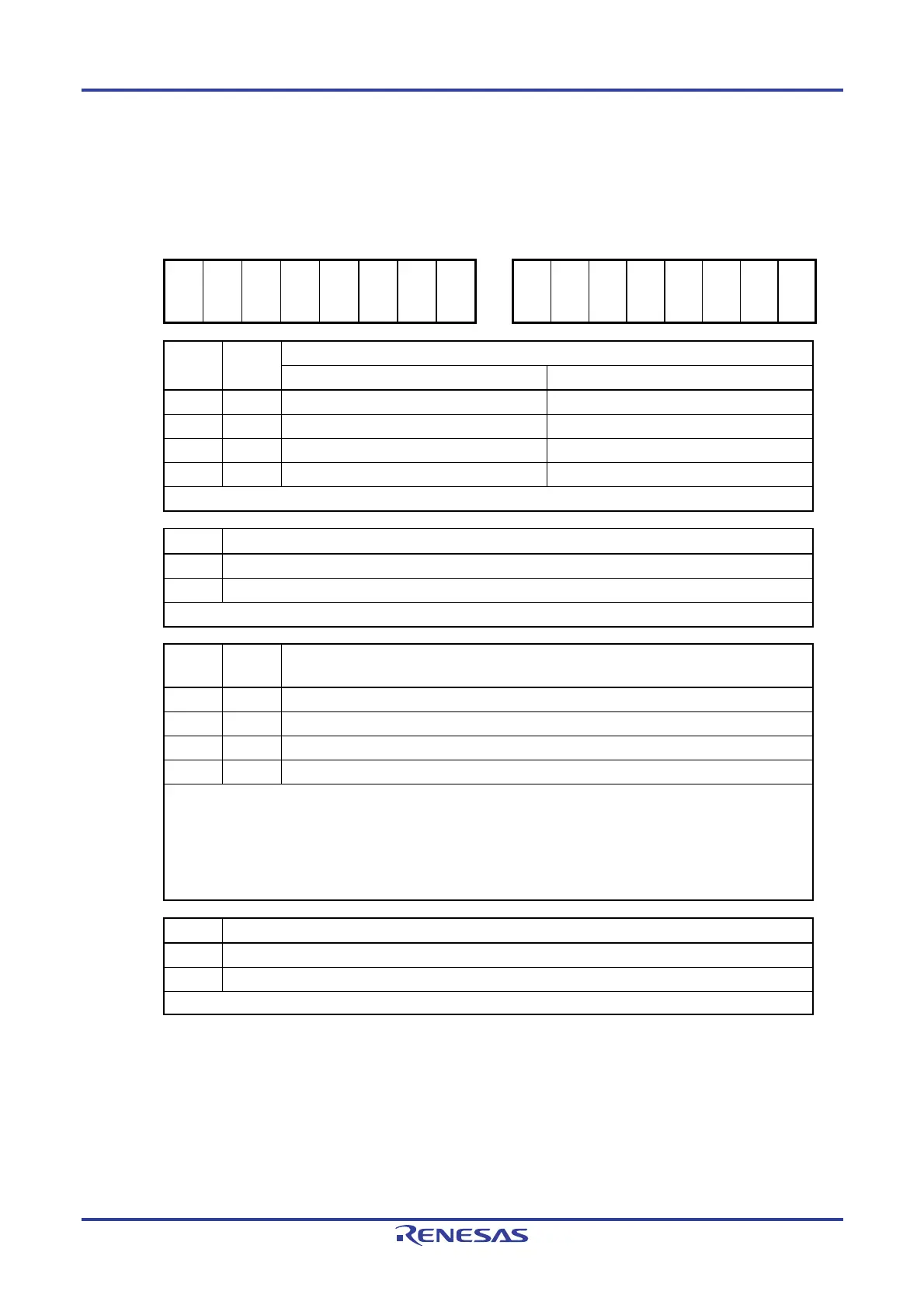
Figure 12-6. Format of Serial Communication Operation Setting Register 0n (SCR0nH, SCR0nL) (2/2)
Address: F0119H (SCR00H) , F011BH (SCR01H) Address: F0118H (SCR00L) , F011AH (SCR01L)
After reset: 00H R/W After reset: 87H R/W
Symbol: SCR0nH Symbol: SCR0nL
7 6 5 4 3 2 1 0
7 6 5 4 3 2 1 0
TXE
0n
RXE
0n
DAP
0n
CKP
0n
0 EOC
0n
PTC
0n1
PTC
0n0
DIR
0n
0 SLC
0n1
Note 1
SLC
0n0
0 1 1 DLS
0n0
PTC0n1 PTC0n0 Setting of parity bit in UART mode
Transmission Reception
0 0 Does not output the parity bit. Receives without parity
0 1 Outputs 0 parity
Note 2
. No parity judgment
1 0 Outputs even parity. Judged as even parity.
1 1 Outputs odd parity. Judges as odd parity.
Be sure to set PTC0n1, PTC0n0 = 0, 0 in the CSI mode and simplified I
2
C mode.
DIR0n Selection of data transfer sequence in CSI and UART modes
0 Inputs/outputs data with MSB first.
1 Inputs/outputs data with LSB first.
Be sure to clear DIR0n = 0 in the simplified I
2
C mode.
SLC0n1
Note 1
SLC0n0 Setting of stop bit in UART mode
0 0 No stop bit
0 1 Stop bit length = 1 bit
1 0 Stop bit length = 2 bits (n = 0 only)
1 1 Setting prohibited
When the transfer end interrupt is selected, the interrupt is generated when all stop bits have been completely
transferred.
Set the stop bit length to 1 bit (SLC0n1, SLC0n0 = 0, 1) during UART reception and in the simplified I
2
C mode.
Set no stop bit (SLC0n1, SLC0n0 = 0, 0) in the CSI mode.
Set the stop bit length to 1 bit (SLC0n1, SLC0n0 = 0, 1) or 2 bits (SLC0n1, SLC0n0 = 1, 0) during UART
transmission.
DLS0n0 Setting of data length in CSI and UART modes
0
7-bit data length (stored in bits 0 to 6 of the SDR0nL register)
1
8-bit data length (stored in bits 0 to 7 of the SDR0nL register)
Be sure to set DLS0n0 = 1 in the simplified I
2
C mode.
Notes 1. Provided in the SCR00L register only.
2. 0 is always added regardless of the data contents.
Caution Do not change the initial values of the following bits.
SCR0nH: Be sure to clear bit 3 to 0.
SCR00L: Be sure to clear bits 3 and 6 to 0, and set bits 1 and 2 to 1.
SCR01L: Be sure to clear bits 3, 5, and 6 to 0, and set bits 1 and 2 to 1.
Remark n: Channel number (n = 0, 1)

 Loading...


