RL78/G10 CHAPTER 15 KEY INTERRUPT FUNCTION
R01UH0384EJ0311 Rev. 3.11 523
Dec 22, 2016
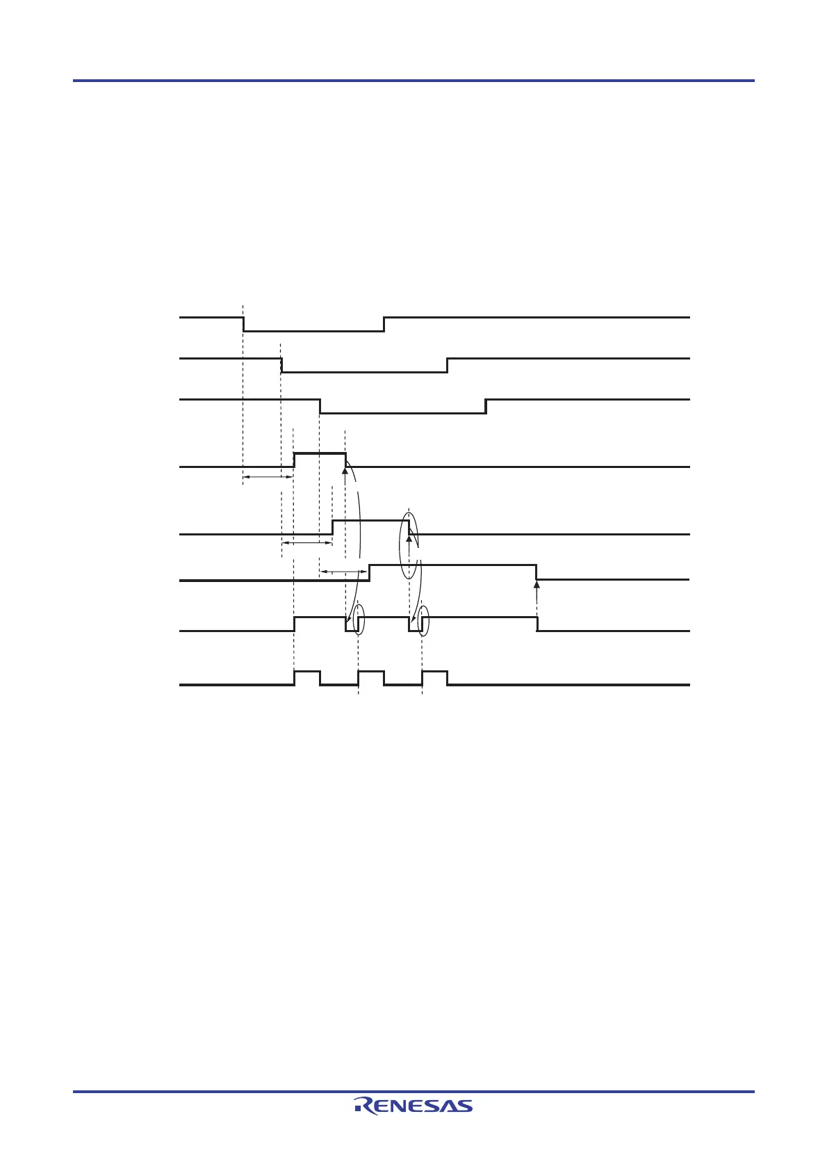
The operation when a valid edge is input to multiple key interrupt input pins is shown in Figure 15-8 below. A falling
edge is also input to the KR1 and KR5 pins after a falling edge was input to the KR0 pin (when KREG = 0). The KRF1 bit
is set when the KRF0 bit is cleared. A key interrupt (INTKR) is therefore generated one clock (f
CLK) after the KRF0 bit is
cleared (<1> in the figure). Also, after a falling edge has been input to the KR5 pin, the KRF5 bit is set (<2> in the figure)
when the KRF1 bit is cleared. A key interrupt (INTKR) is therefore generated one clock (f
CLK) after the KRF1 bit is cleared
(<3> in the figure). It is thus possible to generate a key interrupt (INTKR) when a valid edge is input to multiple channels.
Figure 15-8. Operation of INTKR Signal When Key Interrupts Are Input to Multiple Channels
(When KRMD = 1 and KREG = 0)
KR0
KR1
KR5
<3>
KRF0
<2>
KRF1
KRF5
<1>
INTKR
KRIF
Note
Delay time
Note Note
Clear Clear
Delay time
Delay time
Cleared by software
Cleared by software
Cleared by software
Note Acknowledgment of vectored interrupt request or bit cleared by software
Remark f
CLK: CPU/peripheral hardware clock frequency

 Loading...


