5.39
Date Code 20130214 Instruction Manual SEL-2414 Transformer Monitor
Metering and Monitoring
Monitoring
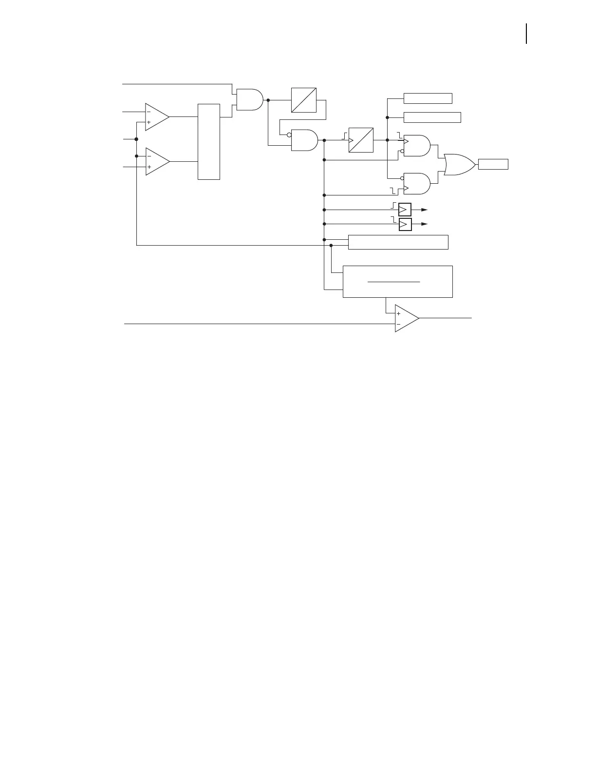
Figure 5.27 Through-Fault Diagram
The 10-cycle Timer avoids the inadvertent increment of the counters or archiving
of the data if the fault current momentarily drops below the lower threshold level.
Setting threshold THFLTPU would usually be set to alarm for excessive,
cumulative transformer bank stress. When the integration exceeds the value as
specified by the THFLTPU setting, Device Word bit TFLTALA asserts. Assign
output Device Word bit TFLTALA to an output for annunciation or control action
such as to modify distribution feeder auto-reclosing (e.g., reduce the number of
reclosures from 3 to 2).
When the fault current falls below 4.5 times the full load level, the element
deasserts, and the following occurs:
➤ The thermal element records the stop time; then calculates (and
records) the fault duration.
➤ The thermal element records the maximum value of the fault
current during the fault.
➤ The integration process stops.
The device can store (archive) the data of 500 through faults in a first-in-first-out
(FIFO) buffer. The element automatically archives the data when one of the
following conditions is true:
➤ The 10-cycle Timer deasserts and the enable signal is de-asserted.
➤ The 10-cycle Timer is de-asserted and the enable signal de-asserts.
Meaning of Accumulated Through-Fault Capability
The through-fault event monitor tracks the effect of each through-fault event and
the cumulative effect of the through-fault events. Based upon the magnitude and
duration of each fault, the event is compared to the through-fault protection curve
shown in Figure 5.26. If the fault is severe enough that it reaches the protection
THFLTPU
ETHRFLT
(Setting)
4.75•I
FULLLOAD
4.5•I
FULLLOAD
IA
S
Q
R
0
1 min
1-minute
Timer
Enable
10-cycle
Timer
0
10
cyc
Total Counter
A-Phase Counter
Archive
Start Time
Stop Time
Maximum Current Calculation
TFLTALA
0.25
t(I
2RMS_pu
)•FREQ
Σ
•100%
)(