4.8
SEL-2414 Transformer Monitor Instruction Manual Date Code 20130214
Logic Functions
General Logic Functions
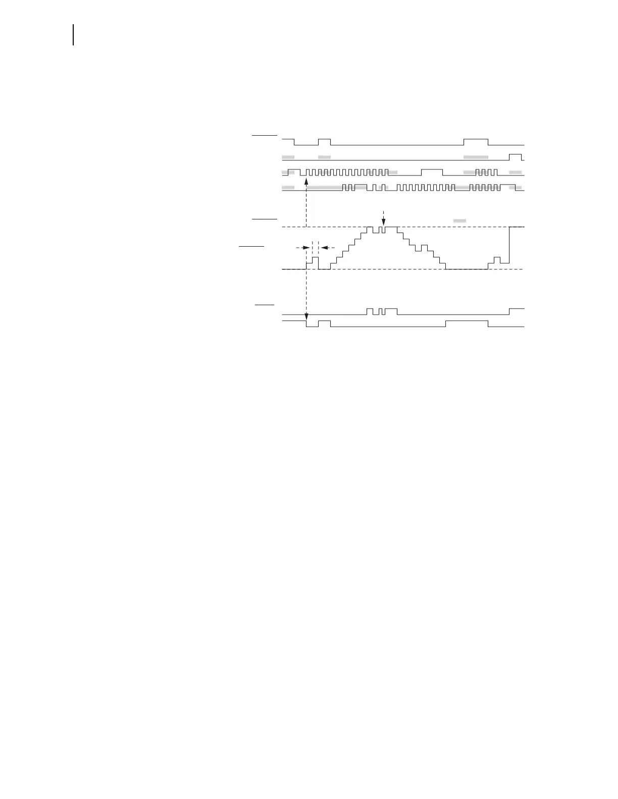
value changing. Most of the pulses in the diagram are on every second processing
interval. The “one processing interval” valley is an example where the CD and
CU pulses are only separated by one processing interval.
The shaded areas illustrate the precedence of the inputs.
When a counter is disabled by setting, the present count value is forced to 0
(SCnn := 0), causing Device Word bit SCnnQD to assert, and Device Word bit
SCnnQU to deassert.
Math Variables
The executed result of a math SELOGIC control equation is stored in a math vari-
able. The storage format of the math variable is a 32-bit fixed point signed inte-
ger; 24 bits represent the integer portion, 7 bits represent the fractional portion,
and one bit represents the sign. The smallest and largest values a math variable
can represent are –16777215.99 and +16777215.99, respectively. If the executed
result exceeds these limits, it will be clipped at the limit value. For example,
when the MV01:= executed result is –16777219.00, MV01 will be
–16777215.99. Similarly, when the MV02 := executed result is +16777238.00,
MV02 will be +16777215.99.
Output Contacts
The SEL-2414 provides the ability to use SELOGIC control equations to map
logic outputs to the physical outputs. You must enter an equation for the output
settings. If you enter, for example, NA, then the device displays the message:
Output Contacts cannot be set to NA, and returns to the output setting. If
you do not want to configure an output contact then enter 0 as the setting, which
is the default setting.
Figure 4.9 Example of the Effects of the Input Precedence
SC01QU
SC01QD
Device
Word
Bits
SC01R
SC01LD
SC01CU
SC01CD
SEL
OGIC
Settings
SC01PV = 7
Setting
SC01
Analog
= Don't Care
One Processing Interval
Two Processing Intervals
6
5
4
3
2
1
0