2.8
SEL-2414 Transformer Monitor Instruction Manual Date Code 20130214
Installation
Card Configuration
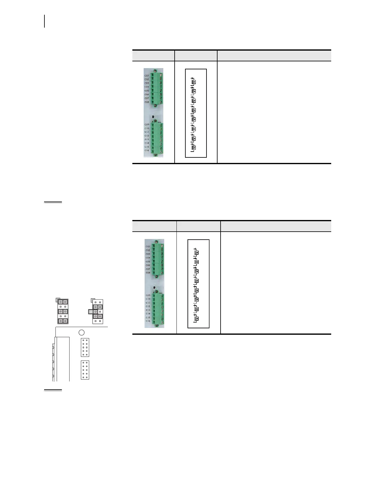
Analog Input Card
(4 AI/4 AO)
Supported in any expansion slot (Slot C through Slot Z), this card has four analog
inputs and four analog outputs (AO). Table 2.11 shows the terminal allocation.
NOTE: Jumper x (x = 1 through 4)
determines the nature of each analog
output channel. Jumper x (x = 5
through 8) determines the nature of
each analog input channel.
NOTE: Maximum of one (1) SELECT
4 AI/4 AO cards per chassis.
Table 2.10 Eight Analog Input Card (8 AI) Terminal Allocation
Term i n al s Label Description
AIx01, Transducer Input number 1
AIx02, Transducer Input number 2
AIx03, Transducer Input number 3
AIx04, Transducer Input number 4
AIx05, Extended Range Transducer Input number 5
AIx06, Extended Range Transducer Input number 6
AIx07, Extended Range Transducer Input number 7
AIx08, Extended Range Transducer Input number 8
AI_02
07
08
05
06
03
04
01
02
AI_01
AI_03
AI_04
13
14
11
12
09
10
AI_05
AI_06
AI_07
15
16
AI_08
For current output (default),
install jumpers between
pins 1–2, 5–6, and 9–10.
For voltage output, install
jumpers between pins 3–4
and 7–8.
For current input, connect the
middle pin with the one labeled I.
For voltage input, connect the
middle pin with the one labeled V.
1
5
9
2
6
10
3
5
7
4
6
8
2
4
6
8
10
1
3
5
7
9
JMP2
2
4
6
8
10
1
3
5
7
9
JMP1
Tab le 2.1 1 Fo u r An al og In p ut/ Fo ur Analog Output Card (SELECT 4AI/4AO)
Terminal Allocation
Term i n a l s Label Description
AOx01, Analog Output number 1
AOx02, Analog Output number 2
AOx03, Analog Output number 3
AOx04, Analog Output number 4
AIx01, Transducer Input number 1
AIx02, Transducer Input number 2
AIx03, Transducer Input number 3
AIx04, Transducer Input number 4
AI_02
07
08
05
06
03
04
01
02
AI_01
AI_03
AI_04
13
14
11
12
09
10
AO_01
AO_02
AO_03
15
16
AO_04