10.10
SEL-2414 Transformer Monitor Instruction Manual Date Code 20130214
Testing and Troubleshooting
Self-Test
Step 3. Using the front-panel SET/SHOW or the serial port SHOW
command, record the CTR, PTR, and PHROT setting values.
Step 4. Apply the current and voltage quantities shown in column 1 of
Table 10.9 and Table 10.10. Values are given for PHROT = ABC
and PHROT = ACB.
Step 5. Use the front-panel METER function or the serial port MET
command to verify the results.
Self-Test
The SEL-2414 runs a variety of self-tests. Two Device Word bits, HALARM and
SALARM, signal self-test problems. SALARM is pulsed for software-pro-
grammed conditions such as settings changes, access level changes, and three
consecutive unsuccessful password entry attempts. HALARM is pulsed for hard-
ware self-test warnings. HALARM is continuously asserted (set to logical 1) for
hardware self-test failures.
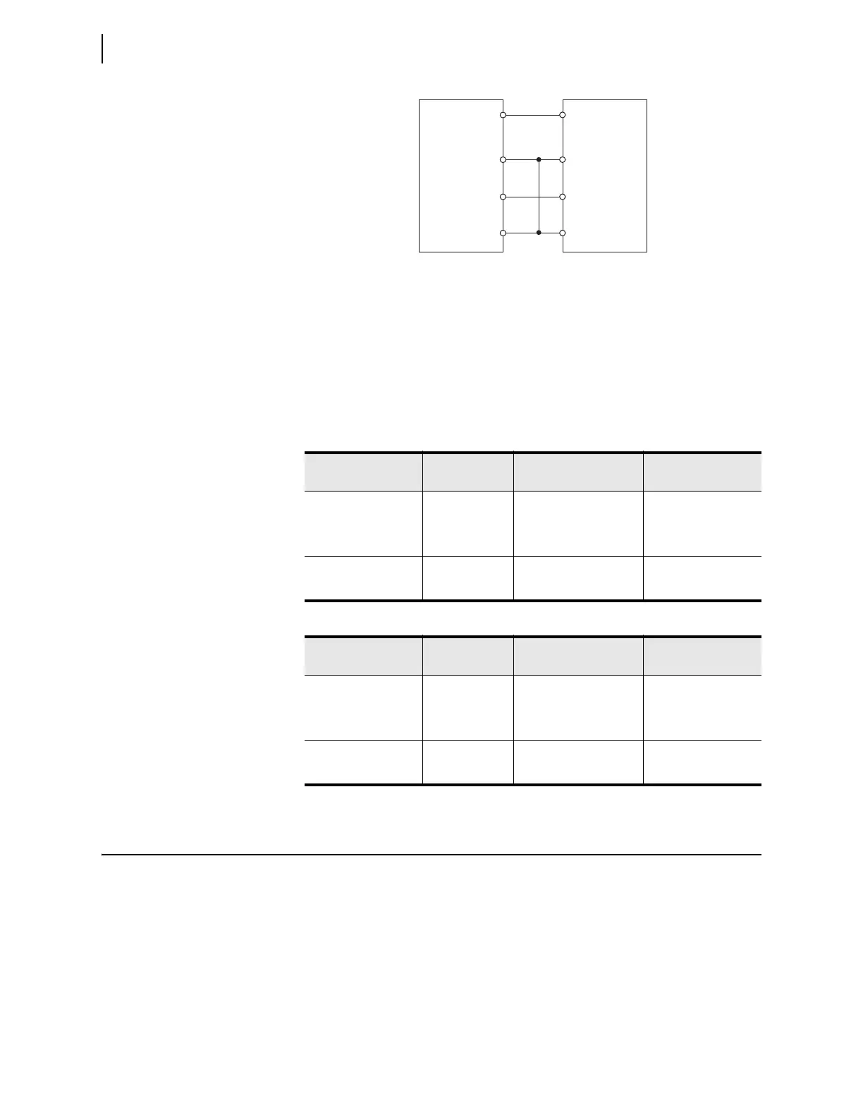
Figure 10.7 Delta Voltage Source Connections
Table 10.9 Current and Voltage Quantities for PHROT = ABC
Applied Currents
and Voltages
Real Power
(kW)
Reactive Power
(kVAR)
Power Factor (pf)
IA = 2.5 ∠ –26 Expected
P = 0.4677 •
CRT1 • PTR
Expected Q = 0.2265 •
CTR • PTR
Expected pf = 0.9 lag
IB = 2.5 ∠ –146
IC = 2.5 ∠ 94
VAB = 120 ∠ 30 Measured: Measured: Measured:
VBC = 120 ∠ 30
Table 10.10 Current and Voltage Quantities for PHROT = ACB
Applied Currents
and Voltages
Real Power
(kW)
Reactive Power
(kVAR)
Power Factor (pf)
IA = 2.5 ∠ –26 Expected
P = 0.4677 •
CTR • PTR
Expected Q = 0.2265 •
CTR • PTR
Expected pf = 0.9 lag
IB = 2.5 ∠ 94
IC = 2.5 ∠ –146
VAB = 120 ∠ –30 Measured: Measured: Measured:
VBC = 120 ∠ 90
SEL-2414
VA
VB
VC
VN
E01
E02
E03
E04
Voltage
Test
Source