6.7
Date Code 20130214 Instruction Manual SEL-2414 Transformer Monitor
Settings
Device Settings (SET Command)
Analog Input Setting Example
Assume we installed an analog card in Slot 3. On Input 1 of this analog card, we
connect a 4–20 mA transducer driven from a device that measures temperature on
a transformer load tap changer mechanism. For this temperature transducer,
4 mA corresponds to –50°C, and 20 mA corresponds to 150°C. You have already
installed the correct hardware jumper (see Section 2: Installation for more infor-
mation) for Input 1 to operate as a current input. At powerup, allow approxi-
mately five seconds for the SEL-2414 to boot up, perform self-diagnostics, and
detect installed cards.
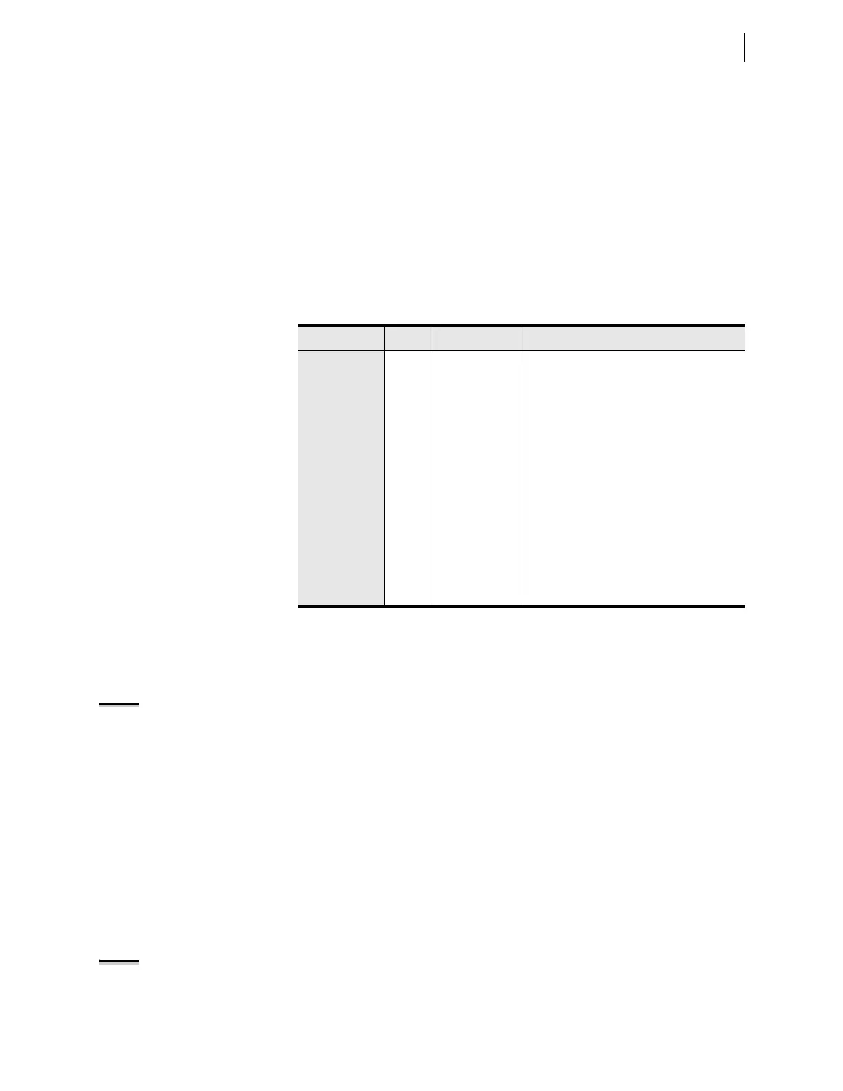
Table 6.7 summarizes the steps and describes the settings we will carry out in this
example.
Because the analog card is in Slot 3, type SET AI301NAM <Enter> (SET with
no setting category assumes the device setting category) to go directly to the set-
ting for Slot 3, Input 1. Although the device accepts alphanumeric characters, the
name AIx0yNAM setting must begin with an alpha character (A through Z) and
not a number. The device displays the following prompt:
NOTE: The AIx0yNAM setting cannot
accept the following:
Analog Quantities
Duplicate Names
Other AI Names
AI301 Instrument Tag Name (8 Chars 0-9,A-Z,_) AI301NAM:= AI301 ?
Use the Instrument Tag Name to give the analog quantity a more descriptive
name. This tag name appears in reports (EVENT, METER, and SUMMARY)
instead of the default name of AI301. SEL
OGIC
®
control equations, signal pro-
files, and Fast Message read use the default names. Use up to eight valid tag
name characters to name the analog quantity. Valid tag names characters are: 0–9,
A–Z, and the underscore (_). For this example, we assign TX_TEMP as the tag
name.
Because this is a 4–20 mA transducer, enter I <Enter> (for current driven
device) at AI301TYP, the next prompt (enter V if this is a voltage-driven device).
The next two settings define the lower level (AI301L) and the upper level
(AI301H) of the transducer. In this example, the low level is 4 mA and the high
level is 20 mA.
AI301 Type (I,V) AI301TYP:= I ?
NOTE: Because the SEL-2414
accepts current values ranging from
–20.48 to 20.48 mA, be sure to enter
the correct range values.
The next three settings define the applicable engineering unit (AI301EU), the
lower level in engineering units (AI301EL) and the upper level in engineering
units (AI301EH). Engineering units refer to actual measured quantities, i.e., tem-
Table 6.7 Summary of Steps
Step Activity Te rse D esc r ip t i on
General
1 SET AI301NAM Access settings for INPUT 1
2 TX_TEMP Enter a Tag name
3 I Select type of analog input; “I” for current
Level
4 Degrees C Enter Engineering unit
5 –50 Enter Engineering unit value LOW
6 150 Enter Engineering unit value HIGH
Low Warning/
Alarm
7 OFF Enter LOW WARNING 1 value
8 OFF Enter LOW WARNING 2 value
9 OFF Enter LOW ALARM value
High Warning/
Alarm
10 65 Enter HIGH WARNING 1 value
11 95 Enter HIGH WARNING 2 value
12 105 Enter HIGH ALARM value