E.2
SEL-2414 Transformer Monitor Instruction Manual Date Code 20130214
Modbus Communications
Function Code Details
Function Code Details
01h Read Discrete
Output Coil Status
Command
Use function code 01h to read the On/Off status of the selected bits (coils) (see
the Modbus Register Map shown in Table E.15). Note that the SEL-2414 coil
addresses start at 0 (e.g., Coil 1 is located at address zero). The coil status is
packed one coil per bit of the data field. The Least Significant Bit (LSB) of the
first data byte contains the starting coil address in the query. The other coils fol-
low towards the high order end of this byte and from low order to high order in
subsequent bytes.
To build the response, the SEL-2414 calculates the number of bytes required to
contain the number of bits requested. If the number of bits requested is not evenly
divisible by eight, the device adds one more byte to maintain the balance of bits,
padded by zeroes to make an even byte. Table E.2 includes the coil number and
lists all possible coils (identified as Outputs and Remote bits) available in the
device. Note that the command depends on the device hardware configuration;
the device responds only to installed cards.
The device responses to errors in the query are shown in Table E.3.
02 Read Input Status
Command
Use function code 02h to read the On/Off status of the selected bits (inputs). You
can read the status of as many as 2000 bits per query. Note that input addresses
start at 0 (e.g., Input 1 is located at address zero). The input status is packed one
input per bit of the data field. The LSB of the first data byte contains the starting
input address in the query. The other inputs follow towards the high order end of
this byte, and from low order to high order in subsequent bytes.
To build the response, the device calculates the number of bytes required to con-
tain the number of bits requested. If the number of bits requested is not evenly
divisible by eight, the device adds one more byte to maintain the balance of bits,
padded by zeroes to make an even byte.
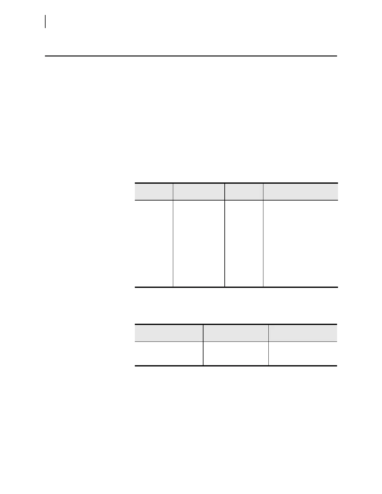
Table E.2 01h Output Coils
Coil Address
in Decimal
Coil Address in Hex
Function Code
Supported
Coil Description
0 0 01h OUT101
1 1 01h OUT102
2 2 01h OUT103
3–10 3–A 01h OUT301–OUT308
a
a
Returns 2 if not installed.
11–18 B–12 01h OUT401–OUT408
a
19–26 13–1A 01h OUT501–OUT508
a
27–34 1B–22 01h OUT601–OUT608
a
35–50 23–32 01h RB01–RB16
51–66 33–42 01h RB17–RB32
Table E.3 Response to 01h Read Discrete Output Coil Status Query Errors
Error Error Code Returned
Communication Counter
Increments
Invalid bit to read Illegal Data Address (02h) Invalid Address
Invalid number of bits to read Illegal Data Value (03h) Illegal Register
Format error Illegal Data Value (03h) Bad Packet Format