10.8
SEL-2414 Transformer Monitor Instruction Manual Date Code 20130214
Testing and Troubleshooting
Functional Testing
Phase Current Measuring Accuracy
The following shows tests for current, voltage, phase angle, and power measure-
ments.
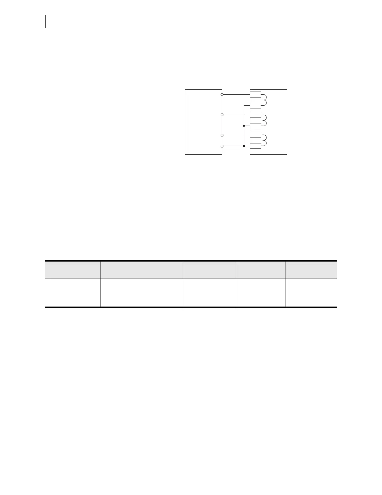
Step 1. Connect the current source to the device, as shown in Figure 10.5.
Step 2. Using the front-panel or the serial port SHOW command, record
the CTR and PHROT setting values.
Step 3. Set the phase current angles to apply balanced three-phase
currents in accordance with the PHROT setting. Refer to
Figure 10.3.
Step 4. Set each phase current magnitude equal to the values listed in
Column 1 of Table 10.6.
Complete Table 10.6 by using the front-panel to view the phase current values.
The device should display the applied current magnitude times the CTR setting.
Power and Power Factor Measuring Accuracy
Wye-Connected Voltages
Perform the following steps to test wye-connected voltages:
Step 1. Connect the current source to the device, as shown in Figure 10.5.
Step 2. Connect the voltage source to the device, as shown in Figure 10.6.
Make sure that DELTA_Y = Wye.
Figure 10.5 Current Source Connections
IA
Z01
Z02
IB
IC
IA
IB
IC
SEL-2414
IN
Current
Test
Source
Z03
Z04
Z05
Z06
Table 10.6 Test Values, Expected Values, and Actual Values
Applied Secondary
Current
a
Expected Reading
(CTR • Applied Current)
A-Phase Reading
(A Primary)
B-Phase Reading
(A Primary)
C-Phase Reading
(A Primary)
0.2 • I
NOM
0.9 • I
NOM
1.6 • I
NOM
a
I
NOM
= rated secondary amps (1 or 5)