10.6
SEL-2414 Transformer Monitor Instruction Manual Date Code 20130214
Testing and Troubleshooting
Functional Testing
Step 8. Using the SET, SET P, SET G, SET R, SET F, and SET L serial
port commands, enter the device settings from the settings sheets
for your application.
Step 9. If you are connecting a fiber-optic cable, follow the substeps
below; otherwise continue with the next step.
a. Connect the fiber-optic cable to the module fiber-optic
output.
b. Plug the device end of the fiber-optic cable into the device
fiber-optic input.
Step 10. Verify the device ac connections.
Step 11. Connect the ac test source current or voltage to the appropriate
device terminals.
IMPORTANT NOTE: Make sure
the current transformer secondary
windings are shorted before they are
disconnected from the device.
Disconnect the current transformer and voltage transformer (if
present) secondaries from the device prior to applying test source
quantities.
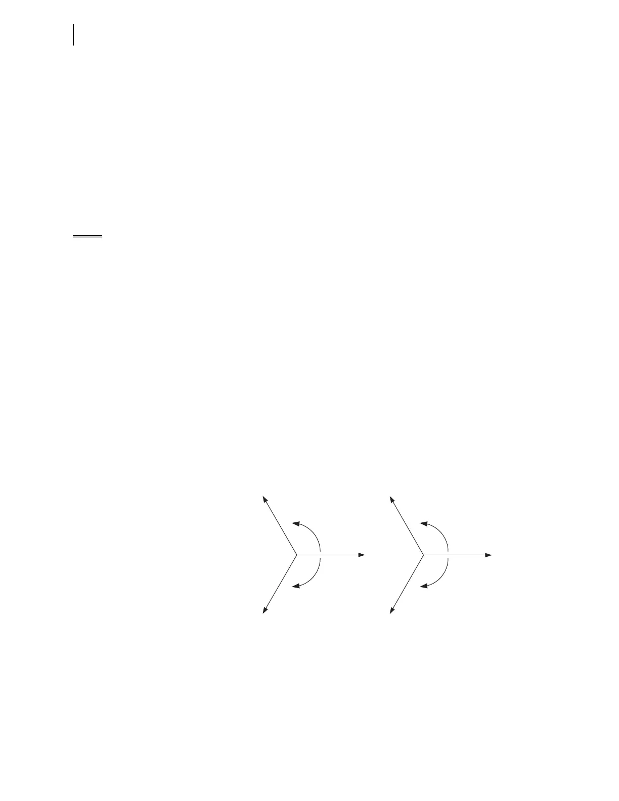
If you set the device to accept phase-to-ground voltages
(DELTA_Y = wye), set the voltage phase angles as shown in
Figure 10.3.
If you set the device to accept delta voltages (DELTA_Y = Delta),
set the current and/or voltage phase angles as shown in
Figure 10.4.
Step 12. Apply rated current (1 A or 5 A).
Step 13. If the device is equipped with voltage inputs, apply rated voltage
for your application.
Step 14. Use the front-panel METER > Fundamental or serial port
METER F command to verify that the device is measuring the
magnitude and phase angle of both voltage and current correctly,
taking into account the device PTR and CTR settings and the fact
that the quantities are displayed in primary units.
Figure 10.3 Three-Phase Wye AC Connections
+120˚
–120˚
V
C
V
B
V
C
V
A
PHROT = ABC
+120˚
–120˚
PHROT = ACB
V
B
V
A
When setting PHROT = ABC, set angle V
a
= angle I
a
= 0˚
set angle V
b
= angle I
b
= –120˚
set angle V
c
= angle I
c
= 120˚
set angle V
a
= angle I
a
= 0˚
set angle V
b
= angle I
b
= 120˚
set angle V
c
= angle I
c
= –120˚
When setting PHROT = ACB,