2.15
Date Code 20130214 Instruction Manual SEL-2414 Transformer Monitor
Installation
Rear-Panel Connections
Power Connections
The POWER terminals on the rear panel (A01(+/H) and A02(—/N)) must connect to
110–240 Vac or 110–250 Vdc or 24–48 Vdc (see Power Supply on page 1.9 for
complete power input specifications.) The POWER terminals are isolated from
chassis ground. Use 16–14 AWG (1.5–2.5 mm
2
) size wire to connect to the
POWER terminals.
Place an external circuit breaker or switch no more than 3.0 m (9.8 feet) from the
equipment. The circuit breaker (or equivalent approved disconnect device appro-
priate for the country of installation) must comply with IEC 60947-1 and
IEC 60947-3 and be identified as the disconnect device for the equipment and be
located near the equipment. This disconnect device must interrupt both the hot
(H) and the neutral (N) power leads.
The maximum current rating for the power disconnect circuit breaker or overcur-
rent device (fuse) must be 20 A. An internal power supply fuse (T315H 250 V)
protects the operational power supply. Be sure to use fuses that comply with
IEC 60127-2.
Grounding
(Earthing)
Connections
Connect the ground terminal labeled GND on the rear of the panel to a rack frame
or switchgear ground for proper safety and performance. Use 14 AWG (2.5 mm
2
)
wire less than 2 m (6.6 feet) in length for the ground connection.
Communications Ports
Serial Ports
Because all ports (F, 2, 3, and 4) are independent, you can communicate to any
combination simultaneously. Although serial Port 4 on the optional communica-
tion card consists of an EIA-485 (4A) and an EIA-232 (4C) port, only one port is
available at a time. Use the Port 4 communication interface COMMINF setting to
select between EIA-485 and EIA-232.
The serial Port 4 EIA-485 plug-in connector accepts wire size AWG 24 through
12. Strip the wires 8 mm (0.31 inches) and install with a small slotted-tip screw-
driver. All EIA-232 ports accept 9-pin D-subminiature male connectors. Port 3
includes the IRIG-B time-code signal input (see below).
Contact with instrument terminals
can cause electrical shock that can
result in injury or death.
!
DANGER
The device contains devices sensitive
to Electrostatic Discharge (ESD).
When working on the device with the
front panel removed, work surfaces
and personnel must be properly
grounded or equipment damage may
result.
!
CAUTION
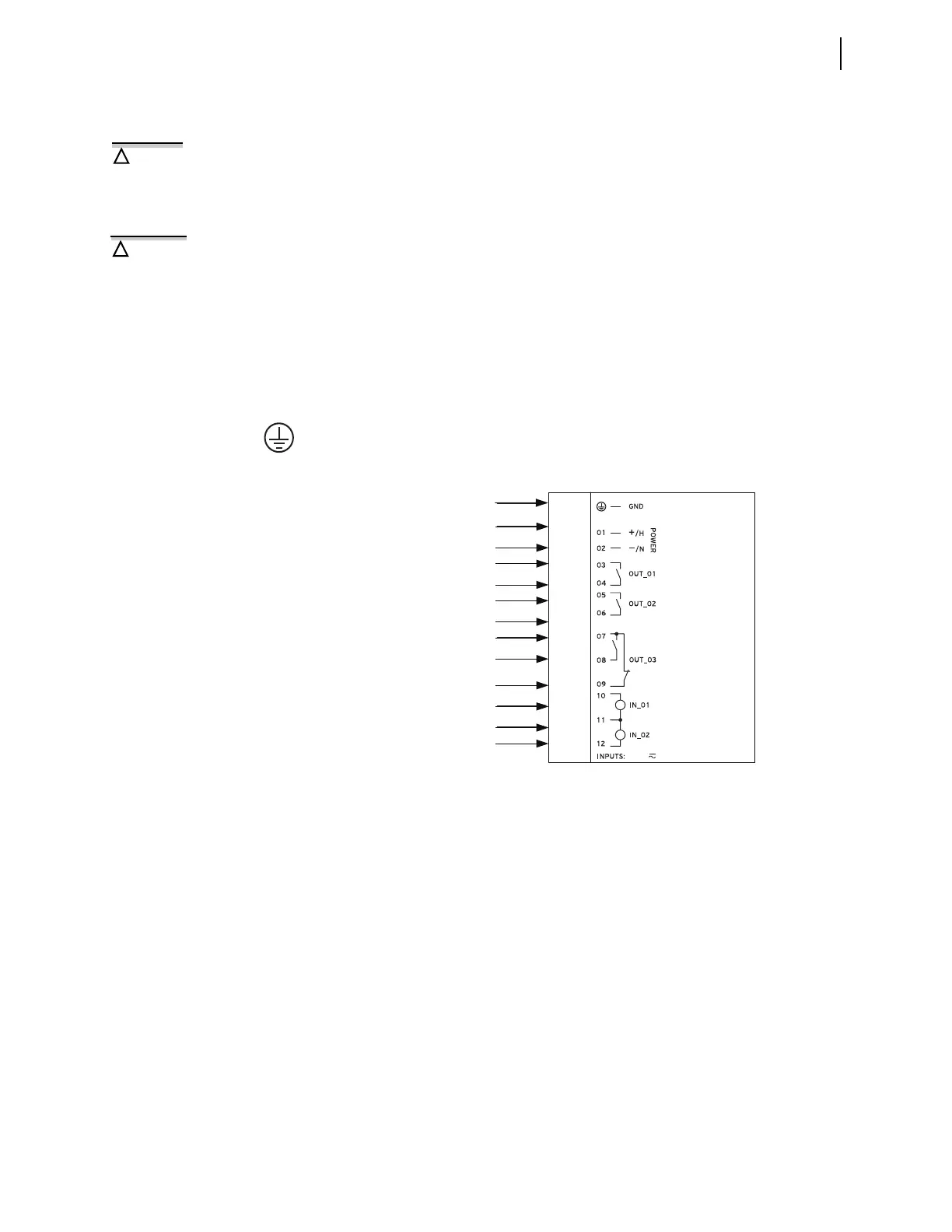
Figure 2.8 Power Connections
A01
A02
A03
A04
A05
A06
A07
A08
A09
A10
A11
A12
SEL-2414
Transformer
Monitor
DC or AC
Power Source
Form A DO
Form A DO
Form C DO
(A07, A08, A09)
Two Optoisolated
DI (A11 common
point for both)
GND