Date Code 20130214 Instruction Manual SEL-2414 Transformer Monitor
Appendix H
Instruction Manual
Device Word Bits
Overview
The protection and control element results are represented by Device Word bits
in the SEL-2414. Each Device Word bit has a label name and can be in either of
the following states:
➤ 1 (logical 1)
➤ 0 (logical 0)
Logical 1 represents an element being picked up or otherwise asserted. Logical 0
represents an element being dropped out or otherwise deasserted. Table H.1 and
Table H.2 show a list of Device Word bits and corresponding descriptions. The
Device Word bit row numbers correspond to the row numbers used in the TAR
command (see TARGET Command (Display Device Word Bit Status) on
page 7.26).
Use any Device Word bit (except Row 0) in SEL
OGIC
®
control equations (see
Section 4: Logic Functions) and the Sequential Events Recorder (SER) trigger
list settings (see Section 9: Analyzing Events).
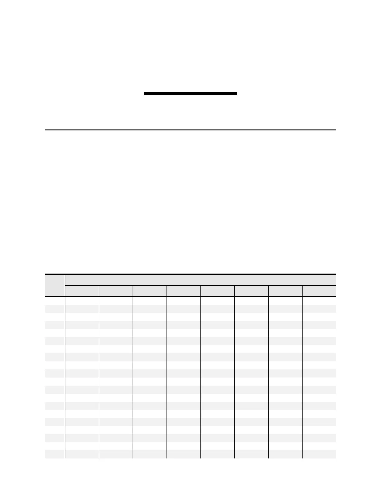
Table H.1 SEL-2414 Device Word Bits (Sheet 1 of 4)
Bit/
Row
Device Word Bits
7 6 5 4 3 2 1 0
TAR 0
ENABLED T00_LED T01_LED T02_LED T03_LED T04_LED T05_LED T06_LED
1
PB01_LED PB02_LED PB03_LED PB04_LED * SALARM IRIGOK HALARM
2
RB01 RB02 RB03 RB04 RB05 RB06 RB07 RB08
3
RB09 RB10 RB11 RB12 RB13 RB14 RB15 RB16
4
RB17 RB18 RB19 RB20 RB21 RB22 RB23 RB24
5
RB25 RB26 RB27 RB28 RB29 RB30 RB31 RB32
6
LB01 LB02 LB03 LB04 LB05 LB06 LB07 LB08
7
LB09 LB10 LB11 LB12 LB13 LB14 LB15 LB16
8
LB17 LB18 LB19 LB20 LB21 LB22 LB23 LB24
9
LB25 LB26 LB27 LB28 LB29 LB30 LB31 LB32
10
SV01 SV02 SV03 SV04 SV05 SV06 SV07 SV08
11
SV01T SV02T SV03T SV04T SV05T SV06T SV07T SV08T
12
SV09 SV10 SV11 SV12 SV13 SV14 SV15 SV16
13
SV09T SV10T SV11T SV12T SV13T SV14T SV15T SV16T
14
SV17 SV18 SV19 SV20 SV21 SV22 SV23 SV24
15
SV17T SV18T SV19T SV20T SV21T SV22T SV23T SV24T
16
SV25 SV26 SV27 SV28 SV29 SV30 SV31 SV32
17
SV25T SV26T SV27T SV28T SV29T SV30T SV31T SV32T
18
SV33 SV34 SV35 SV36 SV37 SV38 SV39 SV40
19
SV33T SV34T SV35T SV36T SV37T SV38T SV39T SV40T