10.4
SEL-2414 Transformer Monitor Instruction Manual Date Code 20130214
Testing and Troubleshooting
Functional Testing
Access the low-level test interface connections by using the following procedure.
The device contains devices sensitive
to Electrostatic Discharge (ESD).
When working on the device with the
front panel removed, work surfaces
and personnel must be properly
grounded or equipment damage may
result.
!
CAUTION
Step 1. Loosen eight (8) mounting (and one ground) screws on the back
and remove the back cover.
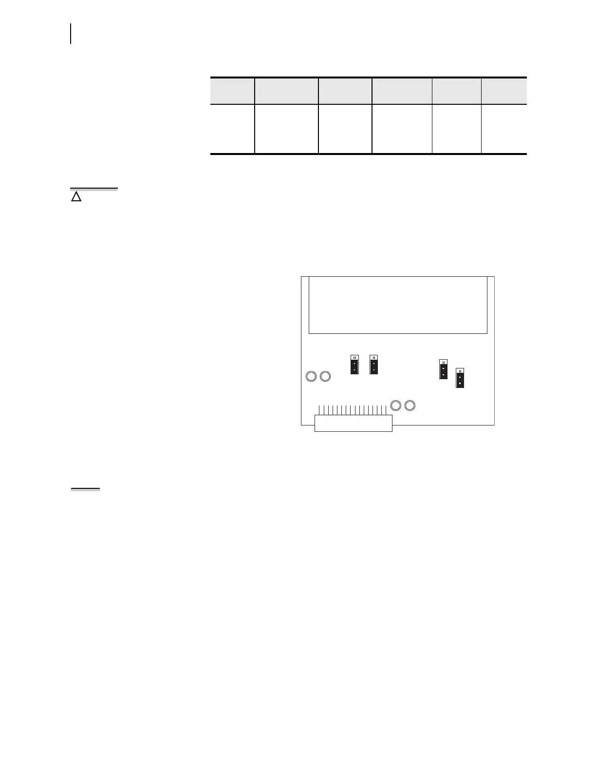
Step 2. Remove the CT board from Slot Z.
Step 3. Locate jumpers JMP1 through JMP4 and change them from the
position labeled CT (Normal position) to position labeled AMS, as
shown in Figure 10.2 (Low-Level Test position).
Step 4. Locate connector J2 and connect low-level signal connector (e.g.,
ribbon cable connector of SEL-RTS Test System).
Step 5. Insert the CT board back in its Slot Z.
Step 6. Remove the voltage board from Slot E.
Step 7. Locate connector J4 and connect low-level signal connector (e.g.,
ribbon cable connector of SEL-RTS Test System).
Step 8. Insert the voltage board back into Slot E.
Refer to the SEL-RTS Instruction Manual for additional detail.
Using the Low-Level Test Interface When Setting DELTA_Y := DELTA
When simulating a delta PT connection with the low-level test interface refer-
enced in Figure 10.1, apply the following signals:
Step 1. Apply low-level test signal VAB to Pin VA.
Step 2. Apply low-level test signal –VBC (equivalent to VCB) to Pin VC.
VBX, 300
V Channel
CT/PT Board /
J1
2 250 V 700.0 mV 357.1 V/V
VCX, 300
V Channel
CT/PT Board /
J1
3 250 V 700.0 mV 357.1 V/V
Table 10.4 Scale Factors for an ACI/AVI Card (Sheet 2 of 2)
Channel
Label
Circuit Board
and Connector
SEL-5401
Channel No.
Nominal Input Output
Scale
Fac tors
Figure 10.2 Jumpers on Current Card to Change to Low-Level
Injection
CT
AMS
CT
AMS
JMP1
JMP2
JMP4JMP3
CT
AMS
NOTE: The 14-pin connectors of the
SEL-RTS ribbon cable C750A can be
used. The connectors are not keyed;
make sure Pin 1 is connected to the
IA/VA channel on the CT and voltage
board, respectively.