2.3
Date Code 20130214 Instruction Manual SEL-2414 Transformer Monitor
Installation
Card Configuration
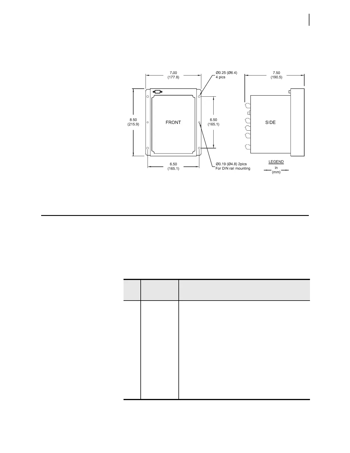
To surface mount the SEL-2414, you can select the SEL-2414 surface mount
option or purchase the surface mount bracket accessory kit (part number
915900204). The mounting dimensions for the SEL-2414 surface mount is
shown below in Figure 2.2.
Card Configuration
Your SEL-2414 offers complete flexibility in tailoring to your specific applica-
tion. The SEL-2414 has six rear-panel slots, labeled as Slots A, B, C, D, E, and Z.
Slot A and Slot B are fixed, but you can install option cards in expansion Slot C
through Slot Z. Except for the input/output cards that can be installed in any
expansion slot (Slot C through Slot Z), you must install the option cards in spe-
cific slots on the device. Table 2.1 shows the slot allocations for the option cards.
Figure 2.2 Transformer Monitor Surface-Mount Dimensions
Table 2.1 Slot Allocations for Different Option Cards
Rear-
Panel
Slot
Software
Reference
Description
A 1 (e.g., OUT101) Power Supply (Required in Slot A)
B N/A CPU Card (Required in Slot B)
CPU Card + Rear Fiber Serial Port
CPU Card + One or Two (Failover) Rear Ethernet Ports
CPU Card + Rear Fiber Serial Port +
One or Two (Failover) Rear Ethernet Ports
C 3 (e.g., IN301) Communications Card (Only supported by Slot C)
Input/Output Card (e.g., 8DI, 8DO, 8AI, ...)
D 4 (e.g., OUT401) RTD/TC Card (Only supported by Slot D)
Input/Output Card (e.g., 8DI, 8DO, 4DI/4DO, ...)
E 5 (e.g., AI501) 3ACI/3AVI Current and Voltage Card (Only supported by Slot E)
Input/Output Card (e.g., 8DI, 8DO, ...)
Z 6 (e.g., OUT601) 4ACI Current Card (Only supported by Slot Z)
Input/Output Card (e.g., 8DI, 8DO, 8AI, 4AI/4AO, ...)