2.12
SEL-2414 Transformer Monitor Instruction Manual Date Code 20130214
Installation
Card Configuration
Use the Level 2 PAR <Enter> (see Section 7: Communications for more infor-
mation) command to update the part number, if required.
Password and
SELBOOT Jumper
Selection
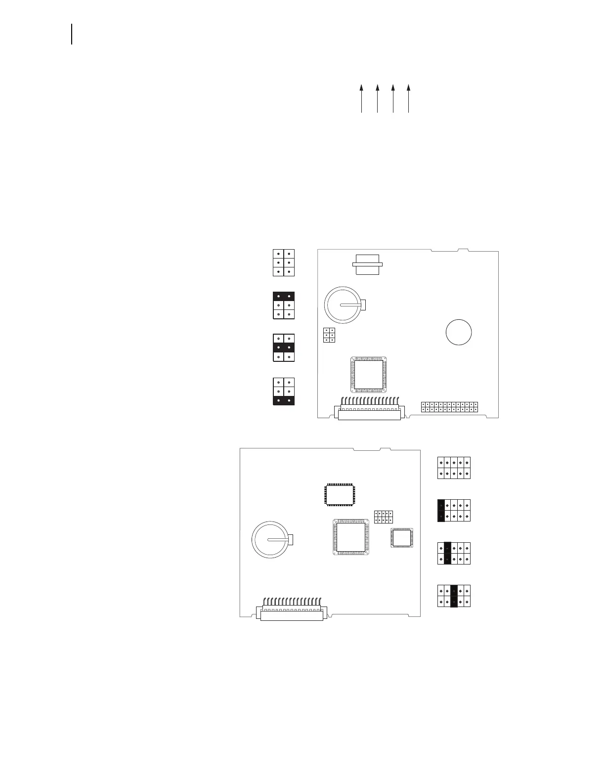
Figure 2.4 shows the major components of the B-slot card in the base unit. Notice
the three sets of pins labeled A, B, and C. Jumper location will vary depending on
your main processor board. Shown below are the two most common locations.
Pins labeled A bypass the password requirement, and pins labeled C force the device to
the SEL operating system called SEL
BOOT (pins labeled B are not used). In the unlikely
event that the SEL-2414 suffers an internal failure, communications with the device
may be compromised. Forcing the device to SEL
BOOT provides a means of download-
ing new firmware. To force the device to SEL
BOOT, position the jumper in position C,
as shown in Figure 2.4 (SEL
BOOT forced). When forced to SELBOOT, you can only
communicate with the device via the front-panel port.
Figure 2.3 Digits That Remain Unchanged After Device Reconfiguration
Figure 2.4 Pins for Password Jumper and SELBOOT Jumper
JMP1
ABC
JMP1
ABC
JMP1
ABC
JMP1
ABC
Password
Bypassed
Default
Positions
SELBOOT
Forced
Not Used
JMP1
(b) Card Layout for Relays With Firmware Versions R302 and Higher
(a) Card Layout for Relays With Firmware Versions Lower Than R302
A
B
C
JMP1
A
B
C
JMP1
A
B
C
JMP1
Default
Positions
Password
Bypassed
Not Used
A
B
C
JMP1
SELBOOT
Forced
A
B
C
JMP1
A B C