5.15
Date Code 20130214 Instruction Manual SEL-2414 Transformer Monitor
Metering and Monitoring
Monitoring
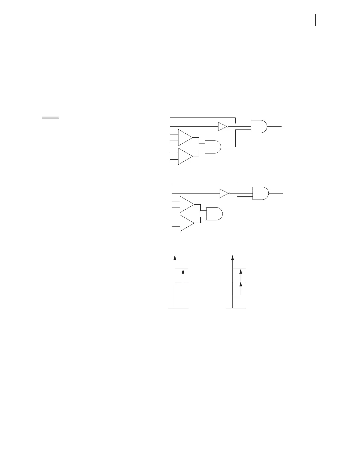
measured top-oil temperature is not available, the thermal element
uses the calculated top-oil temperature as an input to the hot-spot
temperature calculation, as shown in Figure 5.16 (B).
➤ For a single-tank, three-phase transformer (ETHERM = 1), or a
single tank with three sets of three-phase windings (ETHERM =
W), you will have as many as two thermal inputs: the ambient
temperature input and the top-oil input. For independent, single-
phase transformers (ETHERM = 3), you will have as many as four
thermal inputs: an ambient temperature input and a top-oil input
for each of the three tanks.
Figure 5.14 Logic Diagram for MAMB_OK
Figure 5.15 Logic Diagram for MTOX_OK
Figure 5.16 Top-Oil and Hot-Spot Temperatures
Cooling Stage Determination
Cooling stages are defined as follows: Stage 1 is passive cooling (i.e., ONAN),
Stage 2 is the first level of active cooling (i.e., ONAF), and Stage 3 is the second
level of active cooling (i.e., ONAF with second stage fans or OFAF or ODAF).
MAMB_OK
250
AMB_M
AMB_M
—50
AMB_M ≠ OFF
—
+
—
+
AMB_F
NOTE: “x” designates the
transformer; 1, 2, or 3.
MT0x_OK
250
Tx_OILM
Tx_OILM
—50
—
+
—
+
Tx_OIL_F
Tx_OILM ≠ OFF
(A)
ΔΘ
H
ΔΘ
H
ΔΘ
TO
°C
Θ
H
Θ
H
Θ
H
= Calculated hot-spot
temperature using ΔΘ
H
Θ
TO
= Measured top-oil
temperature
Θ
H
= Calculated hot-spot
temperature using ΔΘ
H
and ΔΘ
TO
Θ
TO
= Calculated top-oil
temperature using ΔΘ
TO
Θ
A
= Measured ambient
temperature or from D_AMB setting
Θ
TO
Θ
TO
(B)
°C
Θ
A