4.2
SEL-2414 Transformer Monitor Instruction Manual Date Code 20130214
Logic Functions
Overview
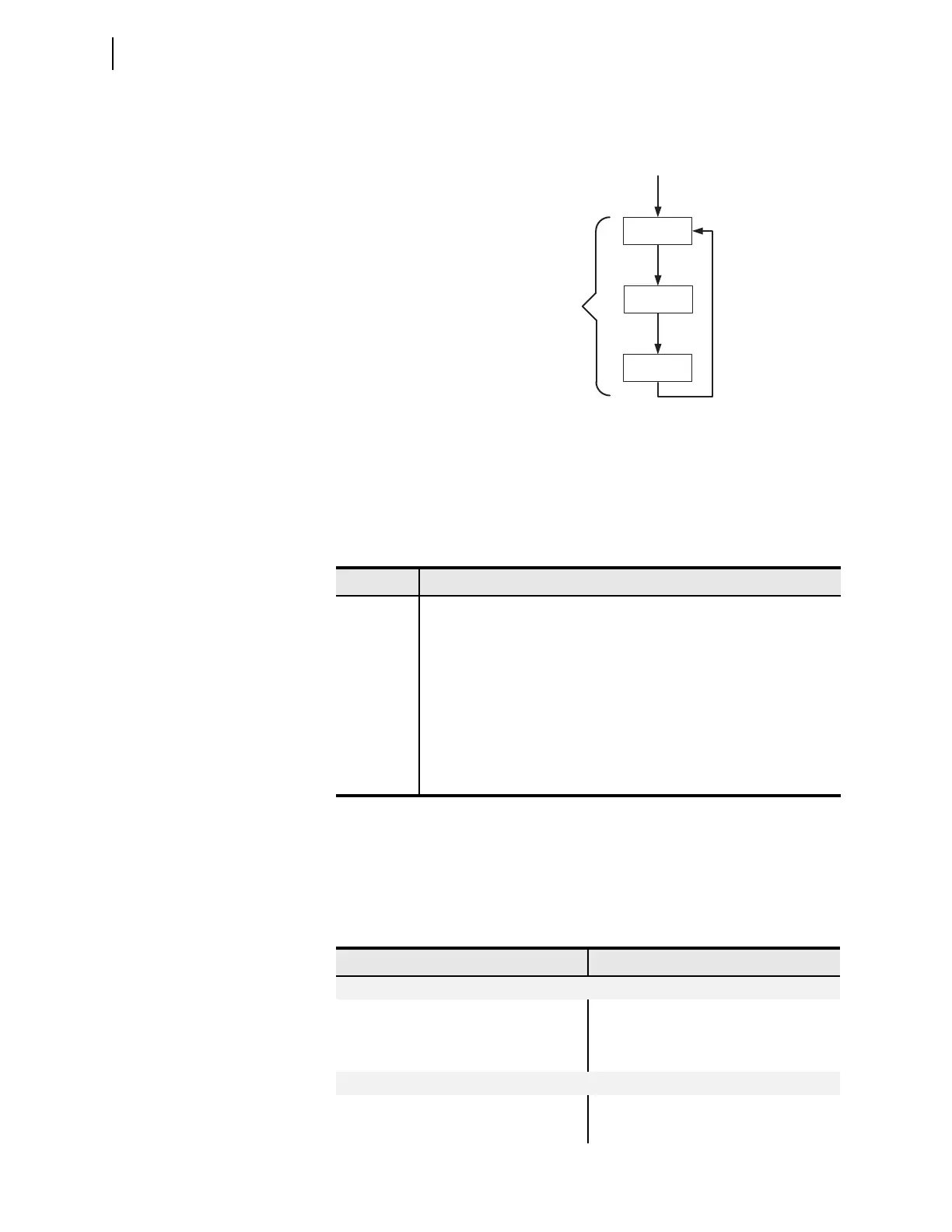
The process of reading the physical inputs, evaluating the logic settings using all
of the inputs and outputs, and operating the physical outputs is shown in
Figure 4.3.
For ease of setting (programming) the device, the settings are grouped into seven
categories as shown in Table 4.1. Many of these categories provide application
specific SEL
OGIC equations that are explained in Section 6: Settings. However,
most of the SEL
OGIC equations and other general-purpose capabilities are pro-
vided by the Logic (SET L) category.
Logical Operators
Logical operators can be used in any SELOGIC equation; they are shown in
Table 4.2. Use the comparison operators with Analog Quantities (e.g., IA, IB,
IC); including Math Variables (MV01–MV32). R_TRIG and F_TRIG only func-
tion with individual word bits. See SEL
OGIC Control Equation Operators for
more details.
Figure 4.3 Operation Sequence
Table 4.1 Setting Categories
Category Description
Global Settings for date format and input debounce timers.
Device Settings associated with analog transducers and current and/or voltage
transformer(s).
Logic Settings associated with latches, timers, counters, and output contacts.
Port Settings that configure the device front- and rear-panel serial ports
(p = F or 3 on the base unit, p = 4 on optional communications card).
Front-Panel Settings for the front-panel display and LED control.
Report Settings for the sequential event reports.
DNP Settings for DNP communications.
Read (Scan)
Inputs
Solve SELOGIC
Write (Scan)
Outputs
Processing Cycle is ~4 ms
(Loop fully executes every
processing cycle.)
Table 4.2 Logical Operators (Sheet 1 of 2)
Operation Operator
Boolean
Boolean AND AND
Boolean OR OR
Complement NOT
Edge Detection
Rising edge trigger/detect R_TRIG
Falling edge trigger/detect F_TRIG