C.7
Date Code 20130214 Instruction Manual SEL-2414 Transformer Monitor
SEL Communications Processors
SEL Communications Processor Example
SEL Communications Processor Example
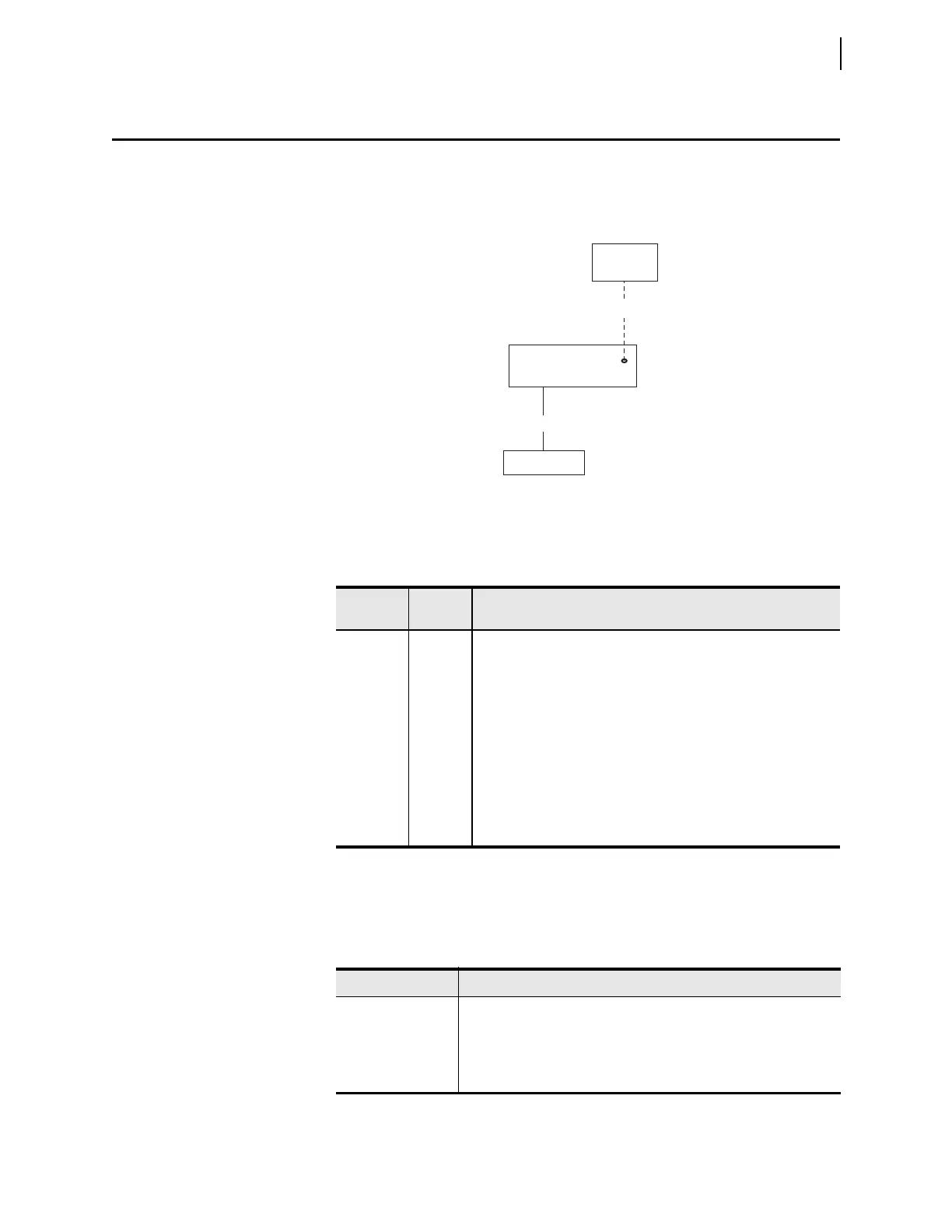
This example demonstrates the data and control points available in the SEL com-
munications processor when you connect an SEL-2414. The physical configura-
tion used in this example is shown in Figure C.4.
Table C.4 shows the Port 1 settings for the SEL communications processor.
Data Collection
The SEL communications processor is configured to collect data from the
SEL-2414, using the list in Table C.5.
Figure C.4 Example SEL Device and SEL Communications Processor
Configuration
Table C.4 SEL Communications Processor Port 1 Settings
Setting
Name
Setting Description
DEVICE S Connected device is an SEL device
CONFIG Y Allow autoconfiguration for this device
PORTID Device 1 Name of connected device
a
a
Automatically collected by the SEL communications processor during autoconfiguration.
BAUD 19200 Channel speed of 19200 bits per second
a
DATABIT 8 Eight data bits
a
STOPBIT 1 One stop bit
PARITY N No parity
RTS_CTS N Hardware flow control enabled
TIMEOUT 30 Idle timeout that terminates transparent connections of 30 seconds
SEL Communications
Processor
SEL-2414
Personal
Computer
Port F
Port 1
Port 3
Cable C273A
Cable C234A
Table C.5 SEL Communications Processor Data Collection Auto-Messages
Message Data Collected
20METER Power system metering data (Binary)
20TARGET Selected Device Word bit elements (Binary)
20HISTORY History Command (CASCII)
20STATUS Status Command (CASCII)