5.5
Date Code 20130214 Instruction Manual SEL-2414 Transformer Monitor
Metering and Monitoring
Metering
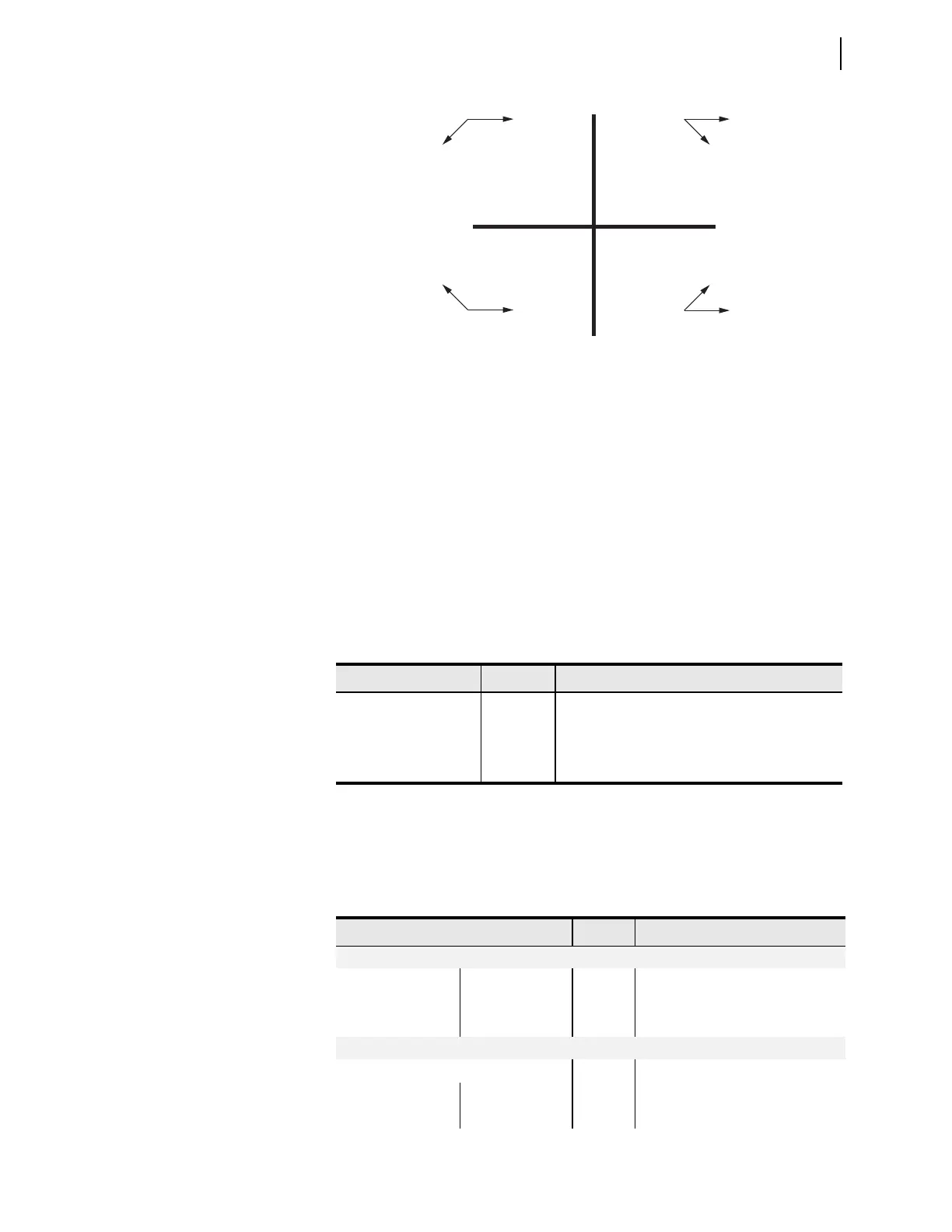
In the SEL-2414, reported positive real power is always into the load. See
Section 7: Communications for examples of the device response to power mea-
surement in the four quadrants.
The device uses a nominal system frequency of 50 or 60 Hz to control the sampling
(data acquisition) of current and voltage waveforms for use in calculating magni-
tudes and angles. If the system frequency deviates from the nominal frequency then
the metering accuracy might degrade. When the device is connected to a three-
phase system then it is able to track the frequency and maintain accuracy.
Energy Metering
The device provides energy metering when current and voltage inputs are
included. Use the MET E command to view real, reactive, and apparent energy
supplied to the load. Table 5.7 lists the energy meter values. To reset energy
meter values, issue the MET RE command.
Maximum and
Minimum Metering
Maximum and minimum metering allows you to determine maximum and
minimum operating quantities such as currents, voltages, power, and frequency.
Table 5.8 lists the max/min metering quantities available with the MET M
command.
Figure 5.4 Complex Power Measurement Conventions—Motor Action
i
v
i
v
Watt = —
VAR = +
II
Watt = +
VAR = +
I
Watt = —
VAR = —
III
Watt = +
VAR = —
IV
pf = leading
pf = lagging
i
v
i
v
pf = lagging
pf = leading
Tab le 5.7 E nerg y Mete r Va lu es
Values Units Description
MWh3P MWh Real 3-Phase Energy (from source to load)
MVARh3P_IN MVAr Reactive 3-Phase Energy (from load to source)
MVARh3P_OUT MVAr Reactive 3-Phase Energy (from source to load)
MVAh3P MVA Apparent 3-Phase Energy
Table 5.8 Maximum/Minimum Meter Values (Sheet 1 of 2)
Values Units Description
Currents (4 ACI) Currents (3 ACI / 3 AVI)
IA, IB, IC, IN IAX, IBX, ICX A Line
IG IGX A Residual Ground
3I2 3I2X A Negative-Sequence
Voltages (3 AVI or 3 ACI / 3 AVI)
VA, VB, VC or VAB, VBC, VCA V Line or Line-Line
VG V Residual Ground
3V2 V Negative-Sequence