2.13
Date Code 20130214 Instruction Manual SEL-2414 Transformer Monitor
Installation
Rear-Panel Connections
To gain access to Level 1 and Level 2 command levels without passwords, posi-
tion the jumper in position A, as shown in Figure 2.4 (Password bypassed).
Although you gain access to Level 2 without a password, the alarm contact still
closes momentarily when accessing Level 2. Table 2.16 tabulates the functions of
the three sets of pins and jumper default positions.
Rear-Panel Connections
Rear-Panel and Side-
Panel Diagrams
The physical layout of the connectors on the rear-panel and side-panel diagrams
of three sample configurations of the SEL-2414 are shown in Figure 2.5,
Figure 2.6, and Figure 2.7.
Table 2.16 Jumper Functions and Default Positions
Pins Jumper Default Position Description
A Not bypassed (requires password) Password bypass
B Not used Not used
C Not bypassed (not forced SEL
BOOT) Forced SELBOOT
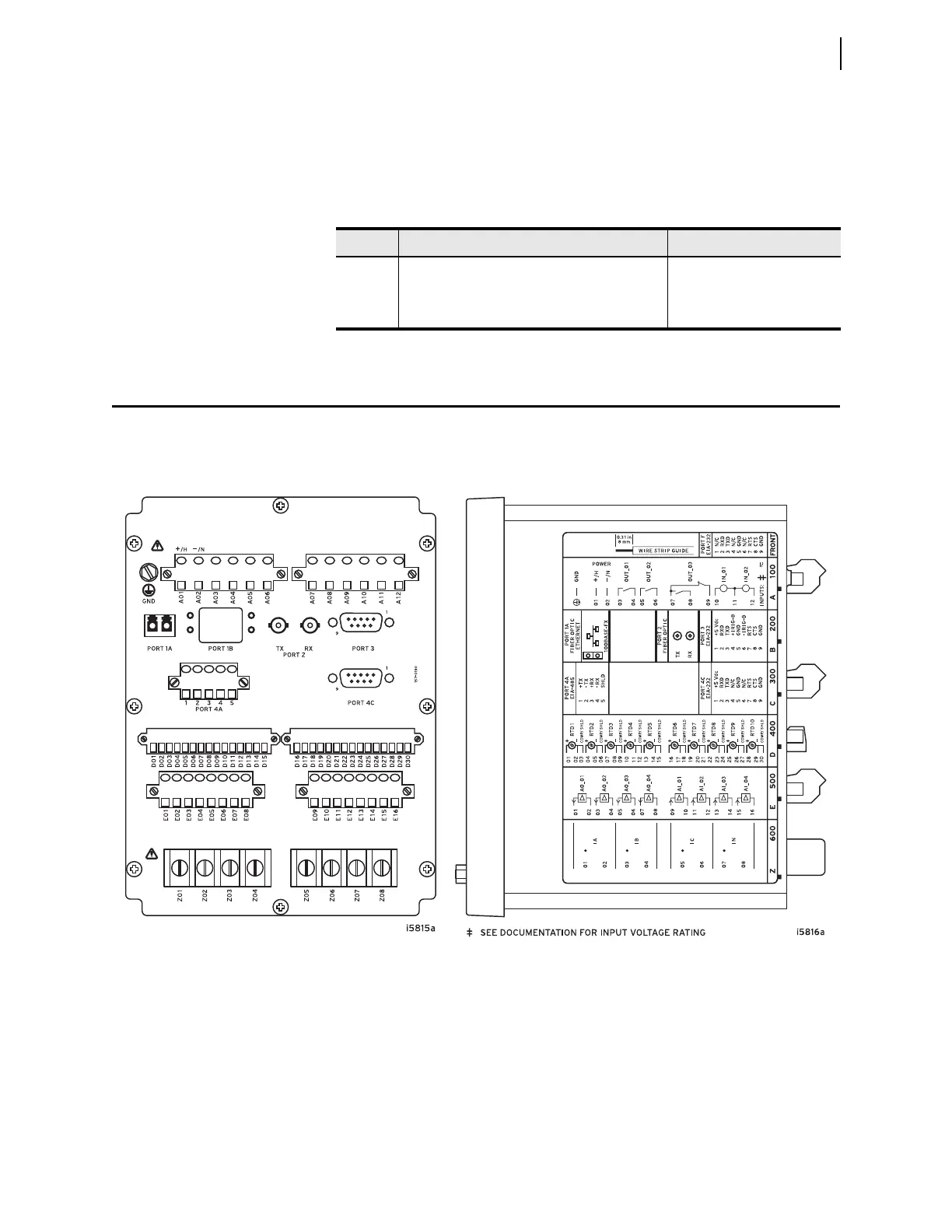
Figure 2.5 Fiber Ethernet, Fiber Serial, Dual EIA-232, 2 DI / 3 DO, EIA-485, 10 RTD, 4 AI / 4 AO, 4 CT
(A) Rear-Panel Layout (B) Side-Panel Input and Output Designations