2.7
Date Code 20130214 Instruction Manual SEL-2414 Transformer Monitor
Installation
Card Configuration
Sampling and Processing Specifications on page 1.10 for more information.
NOTE: The device uses 3I1 to track
the frequency if 3V1 is not available
and 3I1 is greater than 0.25 A (5 A) or
0.05 A (1 A).
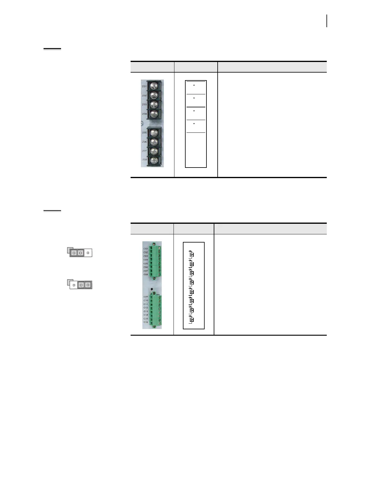
Analog Input Card
(8 AI)
Supported in any expansion slot (Slot C through Slot Z), this card has eight ana-
log inputs (AI). Table 2.9 shows the terminal allocation. Refer to Specifications
for the dc analog inputs ranges.
NOTE: Jumper x (x = 1 through 8)
determines the nature of each
channel
Table 2.8 Current Card (4 ACI) Terminal Designation
Term i n a l s Label Description
IA, Phase A current input
IB, Phase B current input
IC, Phase C current input
IN, neutral current input
For current (default position)
install jumper on JMPX
position 1 – 2.
For voltage, install jumper
on JMPX position 2 – 3.
1 2 3
1 2 3
Table 2.9 Eight Analog Input Card (8 AI) Terminal Allocation
Term i n a l s Label Description
AIx01, Transducer Input number 1
AIx02, Transducer Input number 2
AIx03, Transducer Input number 3
AIx04, Transducer Input number 4
AIx05, Transducer Input number 5
AIx06, Transducer Input number 6
AIx07, Transducer Input number 7
AIx08, Transducer Input number 8
AI_02
07
08
05
06
03
04
01
02
AI_01
AI_03
AI_04
13
14
11
12
09
10
AI_05
AI_06
AI_07
15
16
AI_08