D.11
Date Code 20130214 Instruction Manual SEL-2414 Transformer Monitor
DNP3 Communications
DNP3 in the SEL-2414
Default Data Map
The default data map is an automatically generated subset of the reference map.
All data maps are initialized to the default values, based on the SEL-2414 part
number. Table D.7 shows the SEL-2414 default data map. If the default maps are
not appropriate, you can also use the custom DNP mapping commands SET DN
and SHOW DN to create the map required for your application.
Minimum Metering
30, 32, 34 FREQMN Minimum Frequency
c, g
30, 32, 34 VxMN Minimum, Voltage (x = A, B and C)
c, h
30, 32, 34 VxxMN Minimum, Voltage (xx = AB, BC and CA)
c, h
30, 32, 34 IxMN Minimum, Current Magnitude (x = A, B, C, N and G)
g
30, 32, 34 3I2MN Minimum, Current, Negative Sequence
g
30, 32, 34 KS3PMN Minimum, Apparent Power
b
30, 32, 34 KW3PMN Minimum, Real Power
b
30, 32, 34 KQ3PMN Minimum, Reactive Power
b
30, 32, 34 IxXMN Minimum, Current Magnitude X (x = A, B, C and G)
c
30, 32, 34 3I2XMN Minimum, Current, Negative Sequence X
c
30, 32, 34 KS3PXMN Minimum, Apparent Power X
c
30, 32, 34 KW3PXMN Minimum, Real Power X
c
30, 32, 34 KQ3PXMN Minimum, Reactive Power X
c
Analog Outputs
40, 41 RAxxx Remote Analogs (RA001 to RA128)
a
Although not shown as part of the reference maps, you may use any Device Word bit label when creating custom maps.
b
Valid data only if 4 CT and 3 PT cards are installed in Slots E and Z respectively.
c
Valid data only if 3 CT/3 PT card is installed in Slot E.
d
Valid data only if 10 RTD card is installed in Slot D.
e
Valid data only if SEL-2600 Device is connected via fiber port.
f
Valid data only if IO RTD/TC card is installed in Slot D.
g
Valid data only if 4 CT card is installed in Slot Z.
h
Valid data only if 3 PT card is installed in Slot E.
Tab l e D.6 DN P3 Refe r e nc e D ata M ap
a
(Sheet 3 of 3)
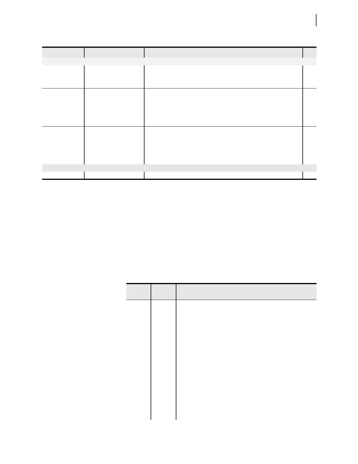
Object Labels Description
Table D.7 DNP3 Default Data Map (Sheet 1 of 2)
Object
Default
Index
Point Label
01, 02 0 ENABLED
1 T01_LED
2 T02_LED
3 T03_LED
4 T04_LED
5 T05_LED
6 T06_LED
7STFAIL
8STWARN
9 IN101
10 IN102
11–200 A portion of these binary inputs can have default values as described
in Binary Inputs. Outside that scope, they contain the value NA.
10, 12 0–31 RB01–RB32 Remote Bits
20, 22 0–7 SC01–SC08 Counters
8–31 NA