2.17
Date Code 20130214 Instruction Manual SEL-2414 Transformer Monitor
Installation
Rear-Panel Connections
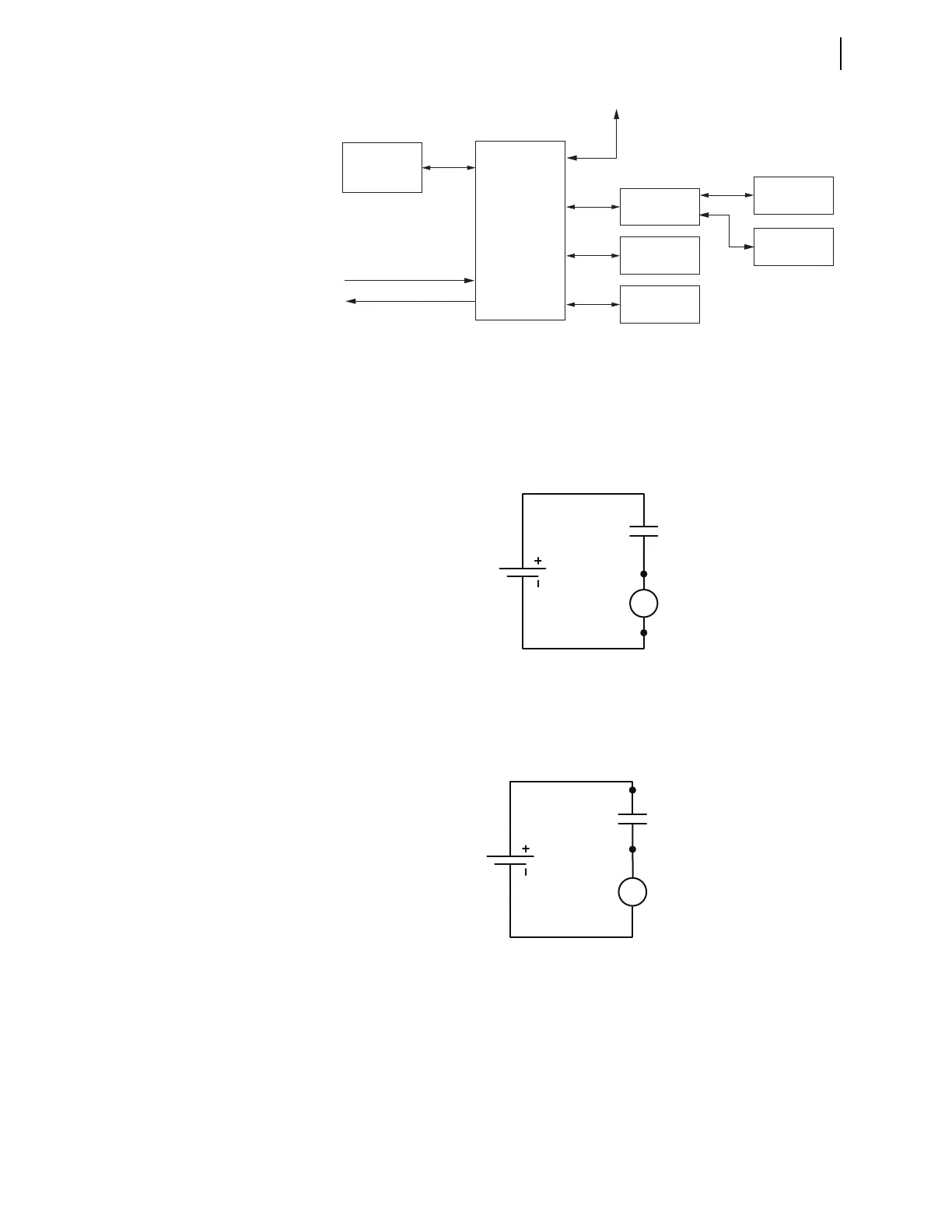
Digital Inputs
The SEL-2414 optoisolated inputs (e.g., IN102, IN404) are not polarity depen-
dent. With nominal control voltage applied, each optoisolated input draws
between 2–6 mA of current. Refer to Section 1: Introduction and Specifications
for optoisolated input ratings. Inputs can be configured to respond to ac or dc
control signals via global settings IN101D–IN102D and IN401D–IN404D.
Digital Outputs
The base unit has standard output contacts only (two Form A and one Form C).
Refer to Section 1: Introduction and Specifications for output contact ratings.
Standard output contacts are not polarity dependent.
Analog Inputs and
Outputs
Be sure to connect wiring to the analog inputs and analog outputs with the correct
polarity. Figure 2.12 shows the device symbol representing an analog input. Con-
nect the positive conductor to Terminal 01 (arrow represents conventional current
flow). Conventional current flow also applies to the analog outputs. You will not
damage the device if you connect the negative conductor to Terminal 01, but con-
necting the negative conductor to Terminal 01 inverts the polarity of the input.
Figure 2.9 Communication Ports
PC
SEL-2725
Ethernet
Switch
SEL Device
M
IRRORED BITS
SEL-3010
Event Messenger
C387
3
2
1B
1A
F
C627
SEL-2414
Transformer
Monitor
PORT 1B
C662
C807
C627
SEL-3530
RTAC
DNP3
Master
C627
C627
IRIG-B OUT
IRIG-B IN
(USB-
Serial)
(Ethernet)
(Fiber)
(Serial)
SEL-2414
Transformer
Monitor
Figure 2.10 Digital Inputs
125 Vdc
IN_01
A10
A11
Figure 2.11 Digital Outputs