E.5
Date Code 20130214 Instruction Manual SEL-2414 Transformer Monitor
Modbus Communications
Function Code Details
The device responses to errors in the query are shown in Table E.10.
10h Preset Multiple
Registers Command
This function code works much like code 06h, except that it allows you to write
multiple registers at once, up to 100 per operation. For six-digit addressing, sim-
ply add 400001 to the standard database addresses.
The device responds to errors in the query as shown in Table E.11.
Reading Event
Summary Data Using
Modbus
Through use of the Modbus Register Map (Table E.15), you can download an
event summary for each of the 30 events stored by the device. The event sum-
mary contains the date and time stamp, type of event that triggered the report,
currents, and voltages at the time of the event. Refer to the Historical Data section
in the map.
To use Modbus to download event summary data, write the event number (1–30)
to the EVENT LOG SEL register at address 0191h. Then read the history of the
specific event number you requested from the registers shown in the Historical
Data section of the Modbus Register Map (Table E.15).
Controlling Output
Contacts and Remote
Bits Using Modbus
The SEL-2414 Modbus Register Map (Table E.15) includes three fields that
allow a Modbus master to force the device to perform a variety of operations. Use
Modbus function codes 06h or 10h to write the appropriate command codes
(Table E.12) and parameters (Table E.13) into the registers (Table E.14). If func-
tion code 06h is used to write to a command code that has parameters, the param-
eters must be written before the command code. After issuing a command,
parameters 1 and 2 are cleared and must be rewritten prior to the next command.
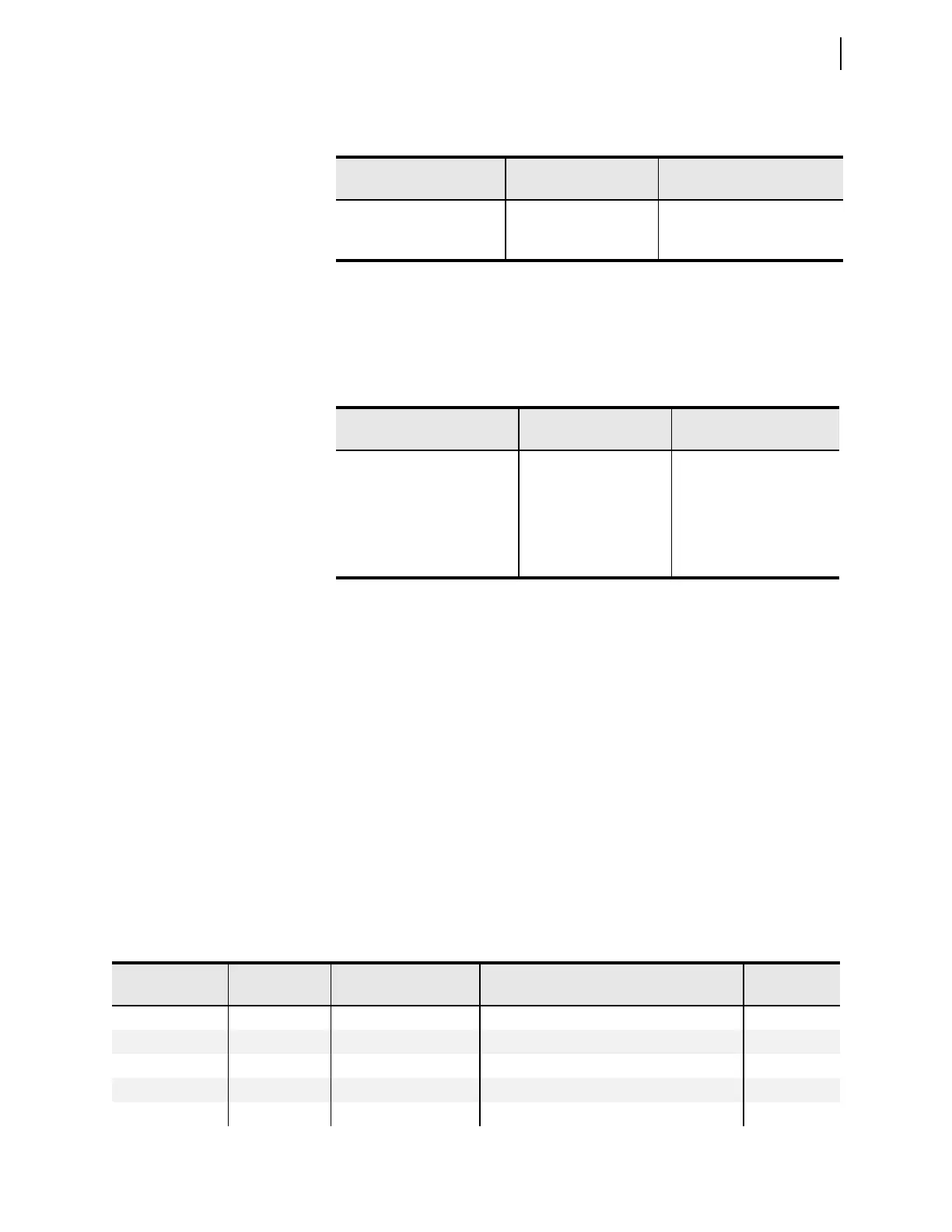
Table E.10 Responses to 06h Preset Single Register Query Errors
Error Error Code Returned
Communication Counter
Increments
Invalid register address Illegal Data Address (02h) Invalid Address Illegal Write
Illegal register value Illegal Data Value (03h) Illegal Write
Format Error Illegal Data Value (03h) Bad Packet Format
Table E.11 10h Preset Multiple Register Query Error Messages
Error Error Code Returned
Communication Counter
Increments
Illegal register to set Illegal Data Address (02h) Invalid Address
Illegal Write
Illegal number of registers to set Illegal Data Value (03h) Illegal Register
Illegal Write
Incorrect number of bytes in
query data region
Illegal Data Value (03h) Bad Packet Format
Illegal Write
Invalid register data value Illegal Data Value (03h) Illegal Write
Table E.12 Command Code Outputs (Sheet 1 of 2)
Command Code in
Decimal
Command Code
in Hex
Function Parameter 1 Parameter 2
11Reset TargetsN/A N/A
2 2 Reserved N/A N/A
3–5 3–5 Pulse OUT101–OUT103 1–30 seconds Duration (Defaults to 1 second) N/A
6–13 6–D Pulse OUT301–OUT308 1–30 seconds Duration (Defaults to 1 second) N/A
14–21 E–15 Pulse OUT401–OUT408 1–30 seconds Duration (Defaults to 1 second) N/A