5.14
SEL-2414 Transformer Monitor Instruction Manual Date Code 20130214
Metering and Monitoring
Monitoring
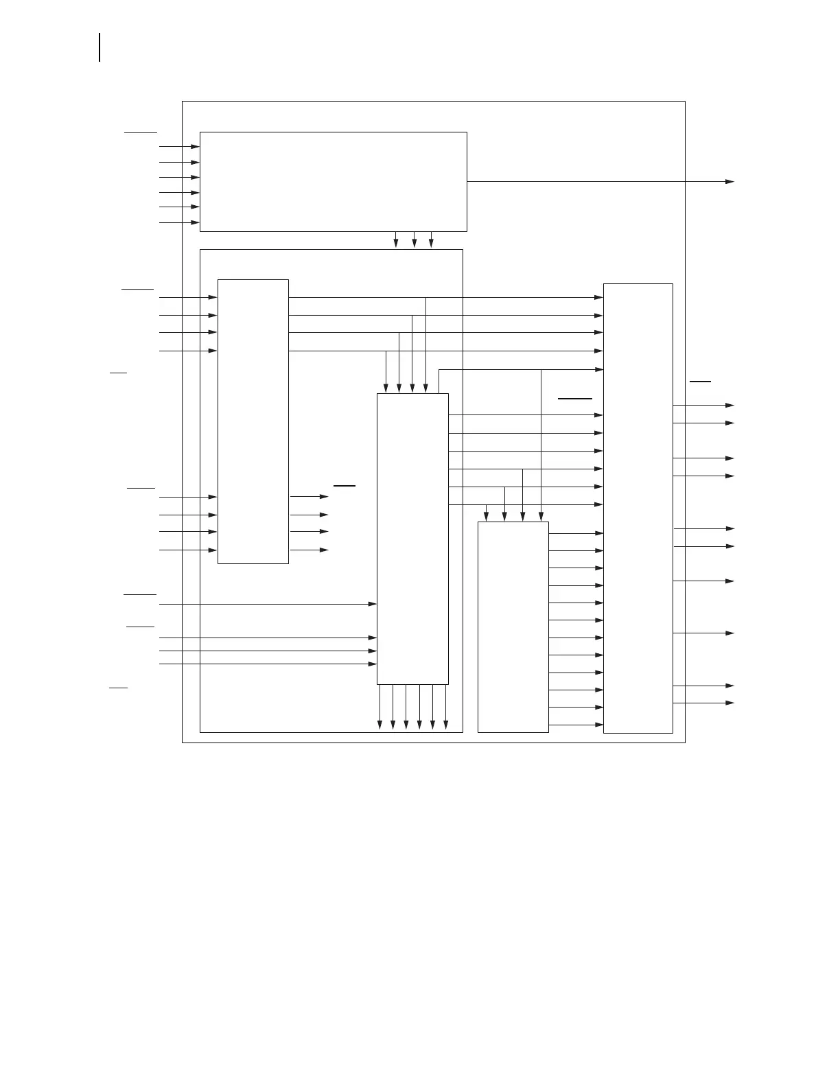
Figure 5.13 Thermal Monitor Block Diagram
Temperature Inputs to the Thermal Element
The thermal element operates with the following temperature inputs:
➤ Ambient Temperature. Measured or default. If a measured value is
not provided or not valid (if MAMB_OK is not asserted, see
Figure 5.14), the thermal element will use the default value
defined by D_AMB.
➤ Top-Oil Temperature. Measured or calculated. If a measured top-
oil temperature is available and valid (if MTOx_OK is asserted,
see Figure 5.15), the thermal element uses that as an input to the
hot-spot temperature calculation, as shown in Figure 5.16 (A). If a
Settings
T1CS2
SEL
OGIC
Equations
T1CS3
T2CS2
T2CS3
T3CS2
T3CS3
AMB_M
T1_OILM
T2_OILM
T3_OILM
AMB_F
T1OIL_F
T2OIL_F
T3OIL_F
Temperature
Acquisition
Top-Oil and
Hot-Spot
Calculations
MAMB_OK
MT01_OK
MT02_OK
MT03_OK
MAMBT
T1OILM
T2OILM
T3OILM
Temperature Calculations
Cooling System Determination Logic
CS1 CS2 CS3
Thermal
Loss-of-Life
Calculations
Analog
Quantities
T1OILC
T2OILC
T3OILC
T1HS
T2HS
T3HS
T1FAA
T2FAA
Thermal
Element
Logic
TO1
TO2
HS1
HS2
FAA1
FAA2
RLL
Device
Word
Bits
CSALARM
Settings
(Analog
Quantity)
Settings
T1LOAD
T2LOAD
T3LOAD
W1LOAD
W2LOAD
W3LOAD
Device
Word
Bits
TRDE
SEL
OGIC
Equations
Note:
Use any of the
following:
RTDs
TCs
Analog Inputs
Remote Analogs
Math Variables
T2RLOL
T3RLOL
T1TLOL
T2TLOL
T3TLOL
T1TLL
T2TLL
T3TLL
T3FAA
T1RLOL
PULOAD
TLL
CSE
CSCM
Settings
Note:
Per unit load current
determined based
on TMWSEL, from
one of the following:
IA,IB,IC / IAX, IBX,
ICX Currents,
Analog Inputs,
Remote Analogs,
or Math Variables
TMWSEL
TMWAQ
MVA[x]CS[y]