7.2
SEL-2414 Transformer Monitor Instruction Manual Date Code 20130214
Communications
Communications
Device Word bits provided for Ethernet ports are shown in Table 7.2.
IRIG-B
Two physical interfaces are available for the demodulated IRIG-B time-code
input. One physical interface is via terminals (B01 and B02), and the other is part
of the serial Port 3 physical interface. Only one interface can be used at a time.
When using serial Port 3, connect to an SEL communications processor with
Cable C273A (see the cable diagrams that follow in this section or use the
SEL-5801 Cable Selector software).
+5 Vdc Power Supply
Serial port power provides as much as 0.5 A total from all of the +5 Vdc pins
(Port F, Port 3, and Port 4A). Some SEL communications devices require the
+5 Vdc power supply. This +5 Vdc is available in any combination of Pins 1, 3,
and 7 without the need for hardware jumpers.
Port Connector and
Communications
Cables
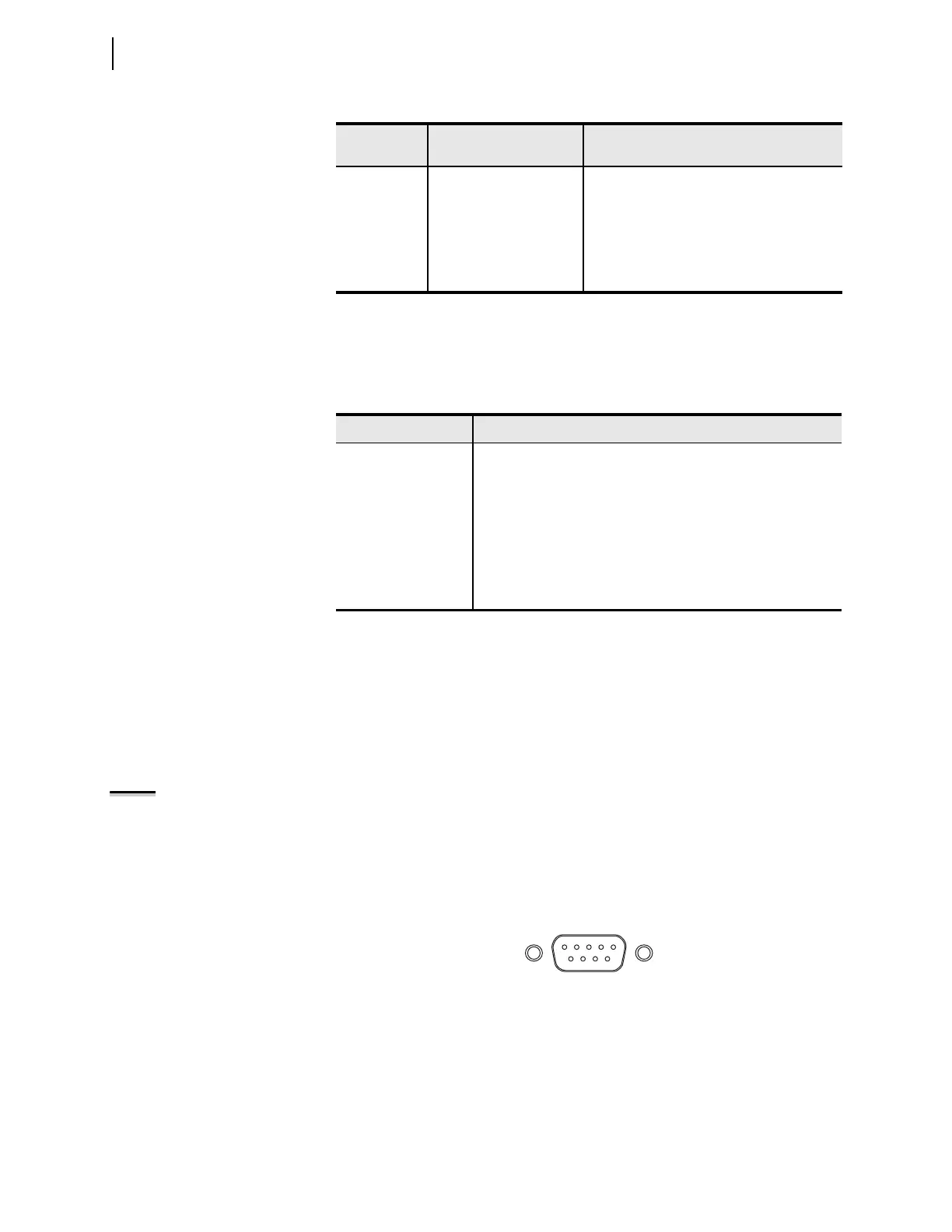
Figure 7.1 shows the front-panel EIA-232 serial port DB-9 connector pin num-
bering for the SEL-2414.
Table 7.3 shows the pin functions for the EIA-232 serial ports.
Port 3, 4A
(Serial)
EIA-232 (Nonisolated) Use the EIA-232 port for communications
distances of ≤15 m (50 feet) in low noise
environments.
Port 4C
(Serial)
EIA
-485 Use the EIA-485 port for communications
distances ≤1200 m (4000 feet). To achieve this
performance, ensure proper line termination at
the receiver.
a
This port can receive RTD measurement information from the optional external SEL-2600
devices. Refer to the applicable SEL
-2600 Instruction Manual for information on the fiber-optic
interface.
Table 7.2 Ethernet Port Device Word Bits
Device Word Bit Description
LINKA Dual Ethernet link status for Port A.
LINKB Dual Ethernet link status for Port B.
LINKFAIL Dual Ethernet active port link status failure indicator. LINKFAIL
asserts if connections fail on both ports for SWITCHED and
FAILOVER operating modes. LINKFAIL asserts if the connection
fails on the primary port for FIXED operating mode.
PASEL Dual Ethernet active Port A indicator.
PBSEL Dual Ethernet active Port B indicator.
Table 7.1 Communications Port Physical Interfaces (Sheet 2 of 2)
Port
Type
Port Interface Usage
NOTE: Although the +5 Vdc power
supply is available at more than one
port, the total 5 V load from any
combination of ports cannot exceed
0.5 A.
Figure 7.1 EIA-232 DB-9 Connector Pin Numbers