5.4
SEL-2414 Transformer Monitor Instruction Manual Date Code 20130214
Metering and Monitoring
Metering
Section 8: Front-Panel Operations and Section 7: Communications describe how
to access the various types of meter data by using the device front-panel and
communications ports.
All angles are displayed between –180 and +180 degrees. All angles are refer-
enced as follows:
Power Measurement Conventions
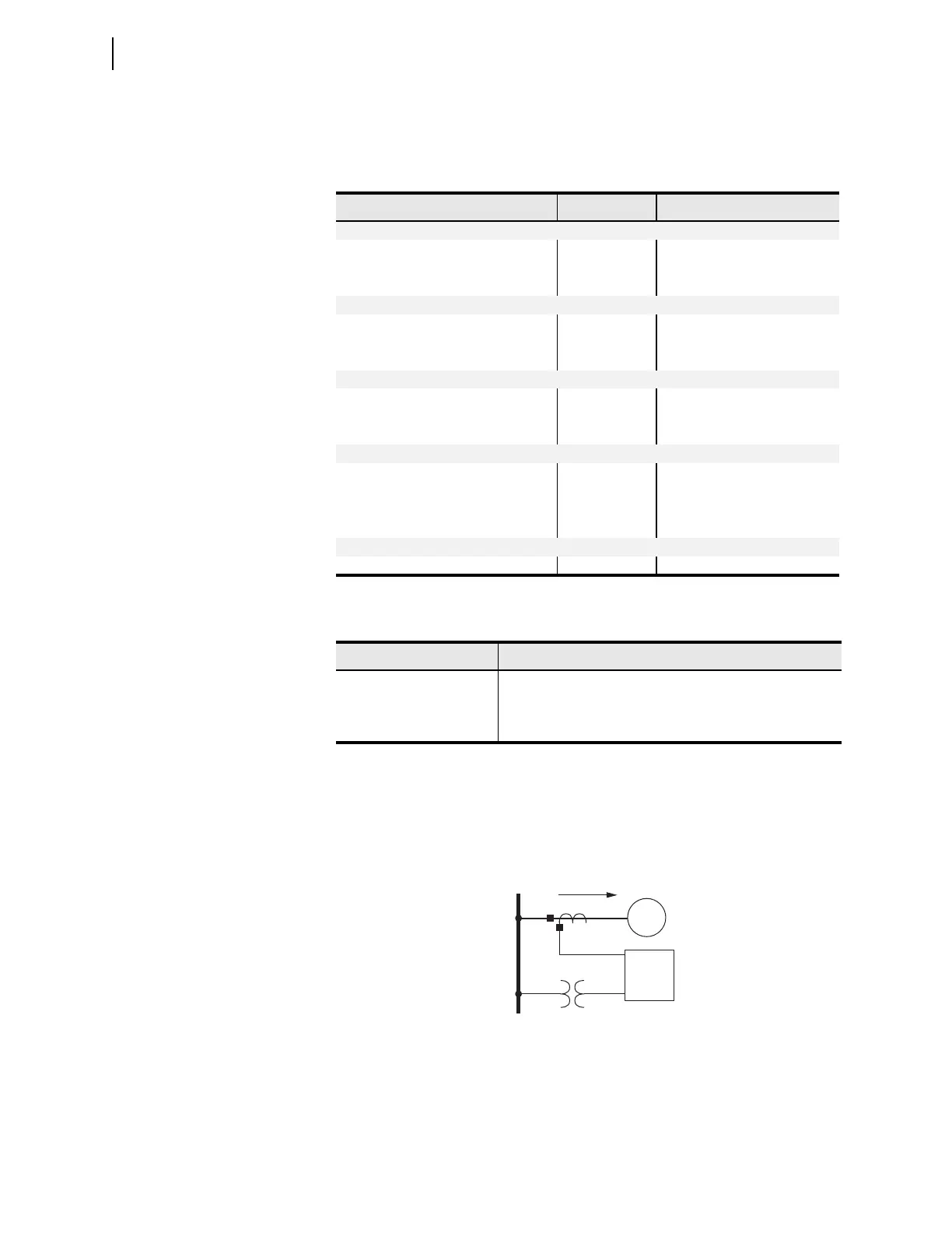
The SEL-2414 uses the IEEE convention for power measurement assuming
motor action, as shown in Figure 5.3 and Figure 5.4.
Figure 5.4 shows the grouping of voltage/current relationships into four quad-
rants (I through IV) as a function of the power factor and the direction of current
flow (i) relative to the applied voltage (v).
Table 5.6 Fundamental Meter Values
Values Units Description
Currents (4 ACI)
IA, IB, IC, IN A, deg Line
IG A, deg Residual Ground
3I2 A Negative-Sequence
Currents (3 ACI/3 AVI)
IAX, IBX, ICX A, deg Line
IGX A, deg Residual Ground
3I2X A Negative-Sequence
Voltages (3 AVI or 3 ACI / 3 AVI)
VA, VB, VC or VAB, VBC, VCA V, deg Line or Line-Line
VG V, deg Residual Ground
3V2 V Negative-Sequence
Power
P kW Real Power
Q kVAr Reactive Power
SkVAApparent Power
PF - Power Factor
Other
HZ Hz System Frequency
Angle Reference Condition
VAN DELTA_Y := WYE and VAN > 13 V
VAB DELTA_Y:= DELTA and VAB > 13 V
IA No voltages or VAN < 13 V or VAB 13 V
Figure 5.3 Primary Plant Connections
SEL-2414
Direction of
Positive Real Power
Source
Bus
Load