TM Palletizing Operator User’s Manual Product Version: 1.0 / Document Version: 1.0 55
4.4 Electric Switchboard inside the Distribution Box
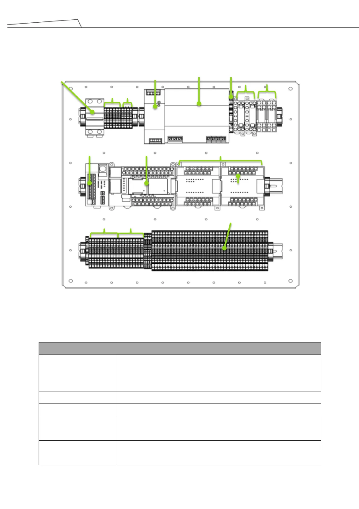
The illustration below shows the I/O components of the electrical switchboard inside the Distribution Box.
Figure 20: Electric switchboard diagram
By default, most of the I/Os on the switchboard are pre-occupied and connected to devices upon shipment. The
table below gives a brief description for each component on the board.
Palletizing I/O are mostly connected to the control box and robotic arm
(TM12) upon shipment. Most of the signals are DIO, Safety I/O and COM.
The only available I/O are for safety outputs SO0 – SO2.
External I/O
(CP1W-20EDT)
• External I/O are occupied by external devices upon shipment.
• The IN_03 can be used to connect to GND to set auto/manual reset.
Safety controller
(G9SP-N20S)
Safety input/output I/O.
• By default, SI0/SI1 are connected to T0/T1 for emergency stop
Palletizing I/O
External I/O (CP1W-20EDT)
Safety controller (G9SP-N20S)
(SF-C21)
AC Power (L/N/PE)
Power supply (2) Power supply (1)
Breaker
Relay
Relay
IN_03