EasyManua.ls Logo

Techman Robot TM Palletizing Operator - Palletizing I;O Pin Definitions; Digital Inputs; Table 17: Pin Signals for DIO, Analog I;O, Safety I;O and COM

Default Icon
176 pages
Print Icon
To Next Page IconTo Next Page
To Previous Page IconTo Previous Page
Loading...
TM Palletizing Operator User’s Manual Product Version: 1.0 / Document Version: 1.0 57
4.5.1 Palletizing I/O Pin Definitions
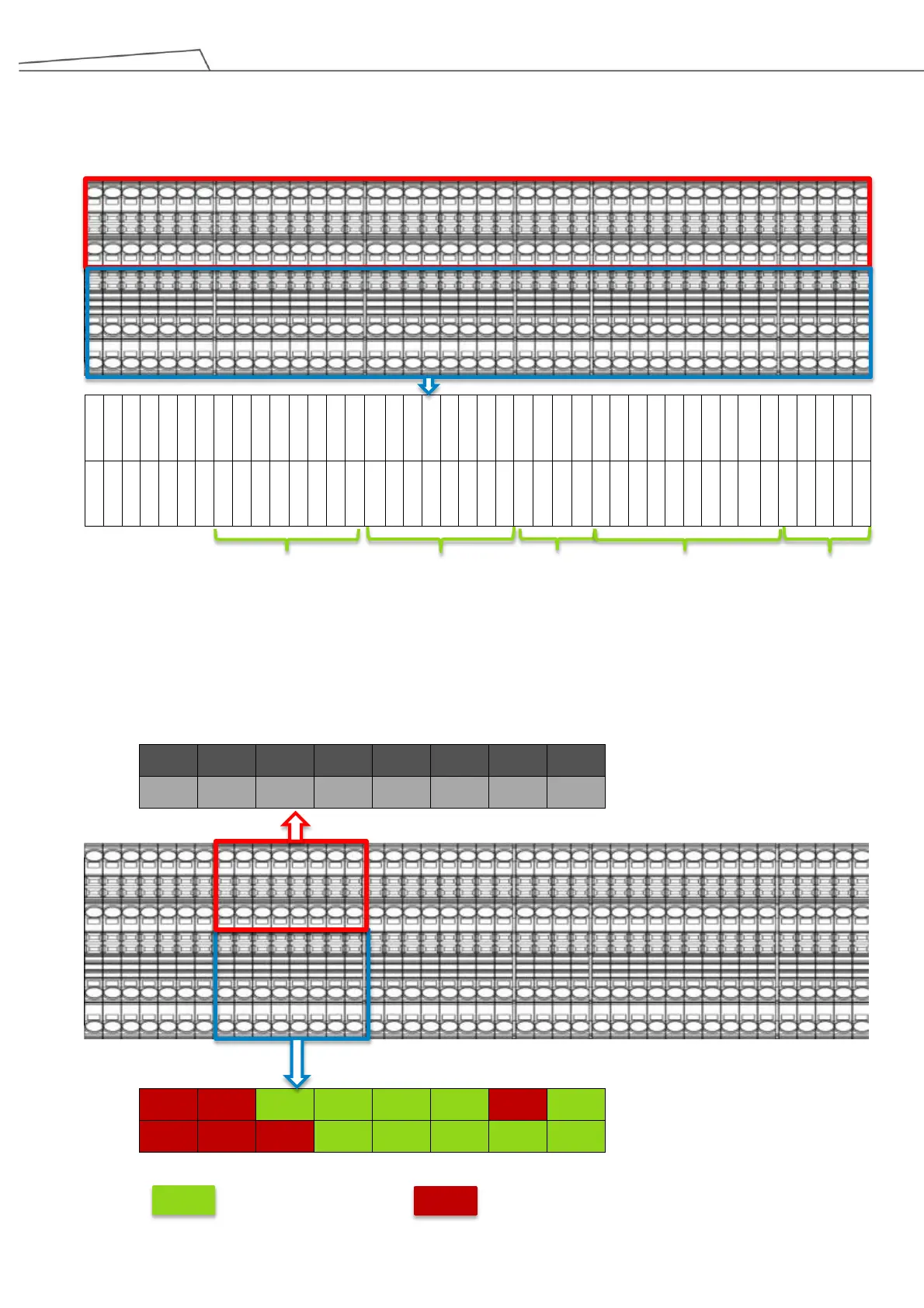
As illustrated below, the I/O highlighted in red indicate that they are reserved for the control box of the
robotic arm, while Table 17 below indicates the I/O signals highlighted in blue.
I_COM
EX-24V
EX-24V
EX-24V
EX-24V
MODE1
MODE2
DI_01
DI_03
DI_05
DI_07
DI_09
DI_11
DI_13
DI_15
DO_01
DO_03
DO_05
DO_07
DO_09
DO_11
DO_13
DO_15
AOUT_G
AIN_0G
AIN_1G
REMO-
SI0_1
SI0_2
SI1_1
SI1_2
SI2_1
SI2_2
SI3_1
SI3_2
SI4_1
SI4_2
SO0_2
SO1_2
SO2_2
SO3_2
SO4_2
O_COM
O_COM
O_COM
O_COM
O_COM
O_COM
O_COM
DI_00
DI_02
DI_04
DI_06
DI_08
DI_10
DI_12
DI_14
DO_00
DO_02
DO_04
DO_06
DO_08
DO_10
DO_12
DO_14
AOUT_V
AIN_0P
AIN_1P
REMO+
SAFE+
SAFE+
SAFE+
SAFE+
SAFE+
SAFE+
SAFE+
SAFE+
SAFE+
SAFE+
SO0_1
SO1_1
SO2_1
SO3_1
SO4_1
Table 17: I/O signals for DIO, Analog I/O, Safety I/O and COM
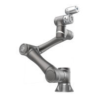
4.5.2 Digital Inputs
Below are Digital Input pin assignments. The I/O highlighted in red are reserved for the control box upon
shipment, while the I/O highlighted in blue come in both reserved and available I/O.
DI_00
DI_02
DI_04
DI_06
DI_08
DI_10
DI_12
DI_14
DI_01
DI_03
DI_05
DI_07
DI_09
DI_11
DI_13
DI_15
DI_01
DI_03
DI_05
DI_07
DI_09
DI_11
DI_13
DI_15
DI_00
DI_02
DI_04
DI_06
DI_08
DI_10
DI_12
DI_14
Digital_IN
Digital_OUT
Analog I/O
Safety_IN
Safety_OUT
Available I/O
Reserved I/O

Table of Contents

Related product manuals