1-16 Instrument description
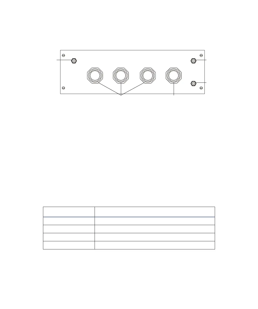
Gas inlet panel
Gas inlet panel
The gas inlet panel has these gas connections:
• Air for the air mount and the source isolation valve. This air supply
must be regulated to 6 bar (90 psi/600 kPa).
• The CI source (CI. 1).
• The First field-free region (FFR.1).
The gas supplies for the CI source and first field-free region must be dry
with a purity of at least 95%. In each case, regulate the supply to <1 bar
(15 psi/100 kPa).
The gas inlet panel also has these manually operated regulator valves:
• Air supply to the air mount and the source isolation valve (inlet).
• Operating the air mount (1, 2 and 3).
Regulator valve functions
Valve Function
Inlet Source isolation valve and input to air mounts
1 Rear air mounts
2 Front air mount (source side)
3 Front air mount (collector side)
OF SPACERS BY 2MM MAX.
INLET123
CI gas
connection
Air
connection
First field-free
region gas
connection
Inlet air regulator valveAir mount regulator valves