5-17
Fuel control unit and component
3. Turn the engine start switch to OFF, and
then remove the fuel cup assembly.
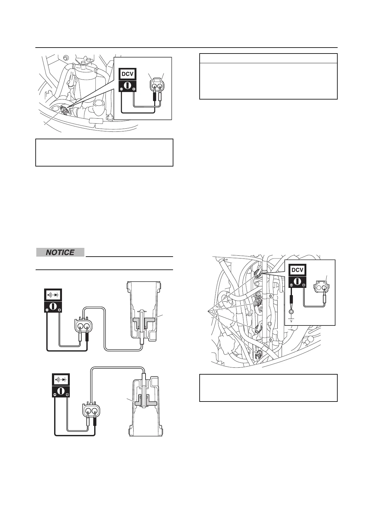
4. Check that the float “1” moves smoothly.
5. Check the water detection switch for con-
tinuity when the float “1” is in positions
“A” and “B”.
Do not remove the clip and float.
6. Install the fuel cup assembly. See “Fuel
filter” (6-7).
7. Connect the water detection switch cou-
pler.
Checking the fuel injector
1. Check the operation of the fuel injectors
using the YDIS “Stationary test” and
check the operating sound.
2. Disconnect the fuel injector couplers “a”.
3. Turn the engine start switch to ON, and
then measure the input voltage between
the fuel injector coupler terminal and
ground.
4. Turn the engine start switch to OFF.
5. Measure the fuel injector resistance.
Water detection switch input voltage:
Blue/White (L/W)–Black (B)
4.75–5.25 V
L/W
B
a
1
A
1
B
Water detection switch continuity:
Continuity:
Float position “B”
No continuity:
Float position “A”
Fuel injector input voltage:
Red/Yellow (R/Y)–Ground
12 V (battery voltage)
R/Y
a