5-41
PTT system
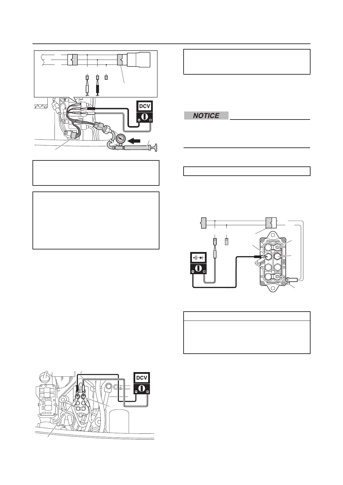
5. Turn the engine start switch to OFF, and
then disconnect the special service tool
and pressure pump.
6. Install the speed sensor, and then con-
nect the speed sensor coupler. See
“Installing the speed sensor” (3-15).
PTT system
Checking the PTT relay
1. Remove the junction box cover
2. Measure the input voltage between the
PTT relay terminal “a” and terminal “b”.
3. Disconnect the battery power source,
ground lead, PTT motor leads, and PTT
relay coupler.
Before disconnecting the PTT relay termi-
nals, make sure to disconnect the battery
negative terminal.
4. Connect the special service tool “1”.
5. Check the PTT relay for continuity.
Replace if out of specification.
6. Connect the positive battery lead to the
terminal “a”, and the negative battery
lead to the terminal “b”, and then check
the PTT relay for continuity. Replace the
PTT relay if out of specification.
Pressure pump “1”:
(commercially available)
Test harness (3 pins) “2”: 90890-06869
Speed sensor output voltage
(reference data):
Blue (L)–Black (B)
2.5 V at 392.0 kPa
(3.92 kgf/cm
2
, 56.8 psi)
4.5 V at 784.0 kPa
(7.84 kgf/cm
2
, 113.7 psi)
L
O
B
BG/W G
2
1
2
a
b
PTT relay input voltage:
Terminal “a”–Terminal “b”
12 V (battery voltage)
Test harness (2 pins) “1”: 90890-06867
PTT relay continuity:
Terminal “b”–Terminal “c”
Terminal “b”–Terminal “d”
Terminal “b”–Terminal “e”
Terminal “d”–Terminal “f”
G/W
G
Lg
Sb
1
e
f
d
c
a
b