5-14
Engine control unit and component
0
1
2
3
4
5
6
7
8
9
10
A
5. Turn the engine start switch to OFF, and
then install the main relay.
Checking the engine ECM circuit
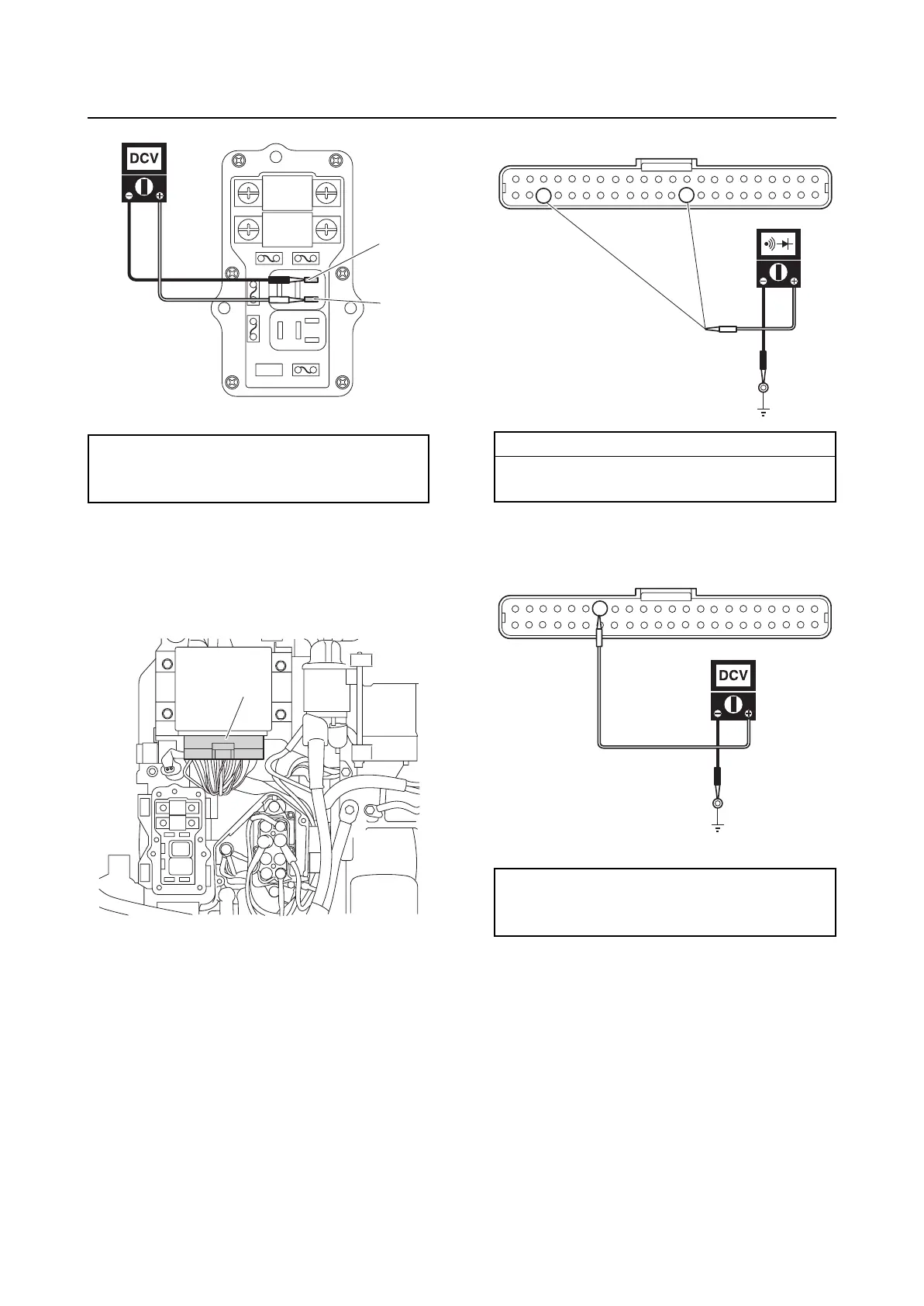
1. Disconnect the engine ECM coupler “a”.
2. Check for continuity between the engine
ECM coupler terminals and ground.
3. Measure the input voltage at the engine
ECM coupler terminal and ground.
4. Turn the engine start switch to ON, and
then measure the input voltage at the
engine ECM coupler terminal and
ground.
Main relay input voltage:
Terminal “a”–Terminal “b”
12 V (battery voltage)
b
a
a
Wiring harness continuity:
Terminal 32–Ground
Terminal 42–Ground
Engine ECM input voltage:
Terminal 16–Ground
12 V (battery voltage)
42
32
16