9-4
Shift rod and shift bracket
0
1
2
3
4
5
6
7
8
9
10
A
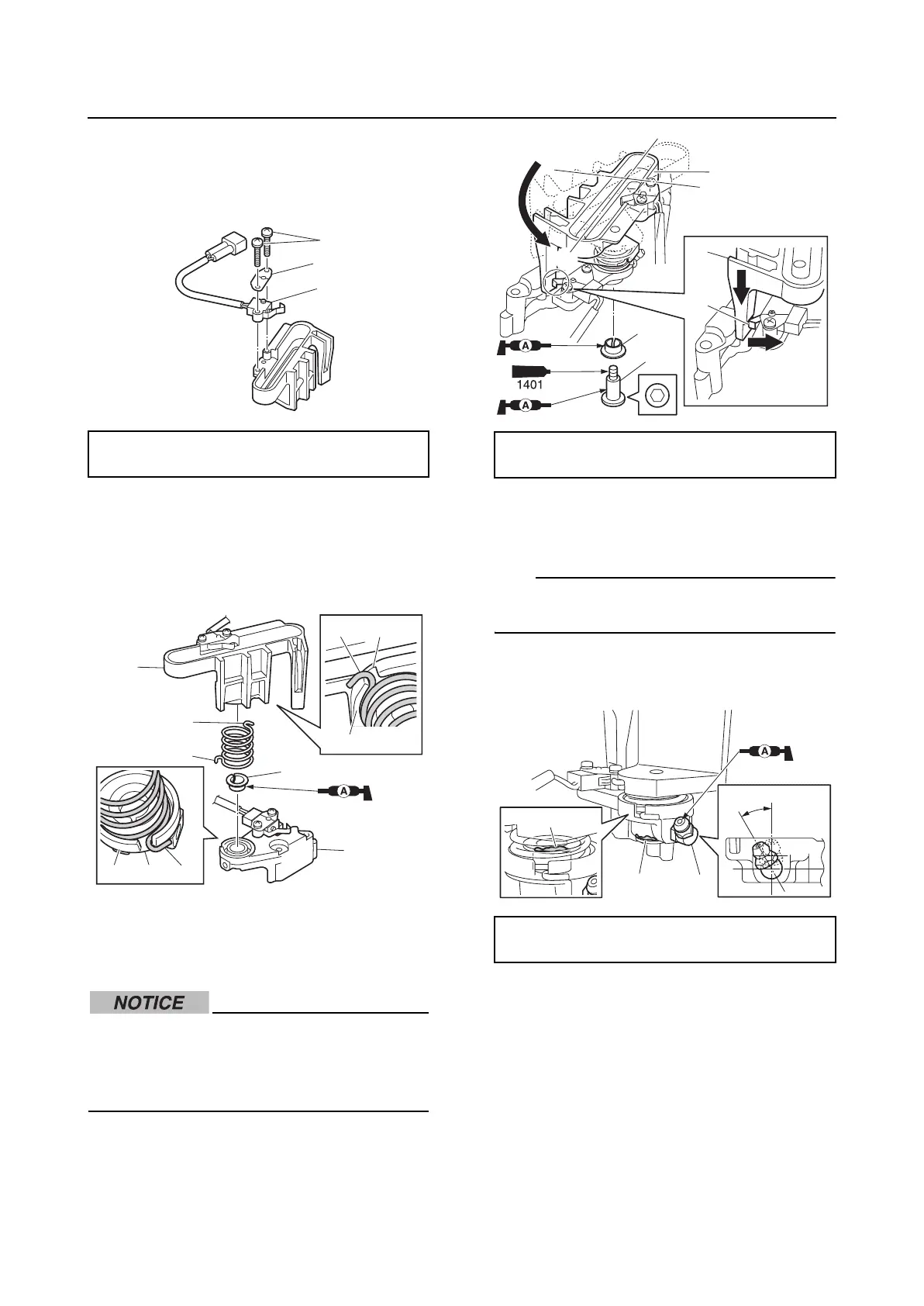
2. Install the shift position switch “1” and
plate “2”, and then tighten the shift posi-
tion switch screws “3” to the specified
torque.
3. Install the bushing “1” to the bracket “2”.
4. Fit the spring end “a” into the cutout “b” in
the bracket “2” and the spring end “c” into
the cutout “d” in the bracket “3”.
5. Turn the bracket “1” to the position “a”,
push it down, and then install the bushing
“2” and shift bracket bolt “3” temporarily.
Move the shift cut-off switch lever “b” in
direction “c” when pushing the shift
bracket “1” down. Otherwise the lever
may be damaged.
6. Tighten the shift bracket bolt “3” to the
specified torque.
7. Install the grease nipple “1”, and then
tighten it to the specified torque.
TIP:
Make sure that the installation angle of the
grease nipple “1” is within the range “a”.
8. Inject grease into the grease nipple until
grease comes out of the bushings “b”.
Installing the shift rod and shift
bracket
1. Install the bushing “1” and washers “2”,
and then install the circlip “3”.
2. Install the ball “4”, spring “5”, and shift
rod detent bolt “6”, and then tighten the
shift rod detent bolt “6” to the specified
torque.
Shift position switch screw “3”:
2.5 N·m (0.25 kgf·m, 1.84 ft·lb)
1
3
2
3
3
2
2
c
a
d
c
a
b
1
Shift bracket bolt “3”:
19 N·m (1.9 kgf·m, 14.0 ft·lb)
Shift bracket grease nipple “1”:
1 N·m (0.1 kgf·m, 0.7 ft·lb)
1
1
3
a
b
c
2
30°
1b
b
a