5-26
Ignition unit and component
0
1
2
3
4
5
6
7
8
9
10
A
c. No continuity
d. Continuity
7. Install the thermoswitch.
8. Connect the thermoswitch connectors.
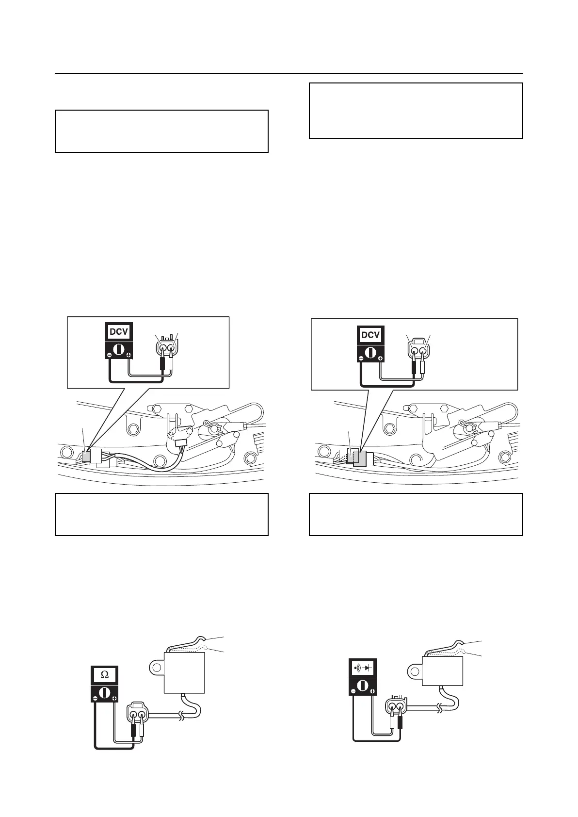
Checking the shift cut-off switch
1. Disconnect the shift cut-off switch cou-
pler “a”.
2. Turn the engine start switch to ON, and
then measure the input voltage at the
shift cut-off switch coupler.
3. Turn the engine start switch to OFF.
4. Remove the shift cut-off switch.
5. Measure the shift cut-off switch resis-
tance.
6. Install the shift cut-off switch. See “Shift
rod and shift bracket” (9-1).
7. Connect the shift cut-off switch coupler.
Checking the shift position switch
1. Disconnect the shift position switch cou-
pler “a”.
2. Turn the engine start switch to ON, and
then measure the input voltage at the
shift position switch coupler.
3. Turn the engine start switch to OFF.
4. Remove the shift position switch.
5. Check the shift position switch for conti-
nuity.
Thermoswitch continuity temperature:
“e”: 84–90 °C (183–194 °F)
“f”: 68–82 °C (154–180 °F)
Shift cut-off switch input voltage:
Blue/Yellow (L/Y)–Black (B)
4.75–5.25 V
L/Y
B
a
a
b
Shift cut-off switch resistance:
4.465–4.935 kΩ at “a” position at
20 °C (68 °F)
0 Ω at “b” position at 20 °C (68 °F)
Shift position switch input voltage:
Blue/Green (L/G)–Black (B)
4.75–5.25 V
L/G
a
B
b
a