5-6
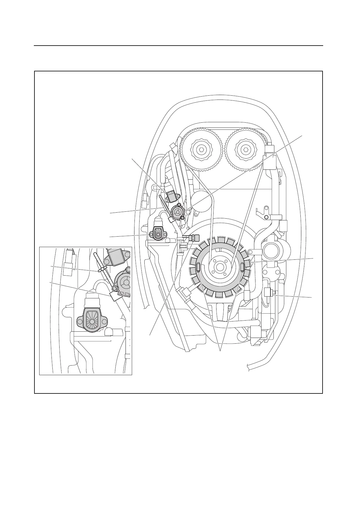
Electrical component and wiring harness routing
0
1
2
3
4
5
6
7
8
9
10
A
Top
1. Air pressure sensor
2. ISC valve
3. Lighting coil (stator assembly)
4. Pulser coil
5. Engine temperature sensor
6. TPS
A. F150A, FL150A
B. F150B, FL150B
D. Install the pulser coil coupler to the junc-
tion box.
E. Bend the engine temperature sensor
lead, and then fasten it using the holder.
F. Fasten the engine temperature sensor
lead using the plastic tie.
4
1
6
E
5
2
3
D
F
E
B
A