6-10
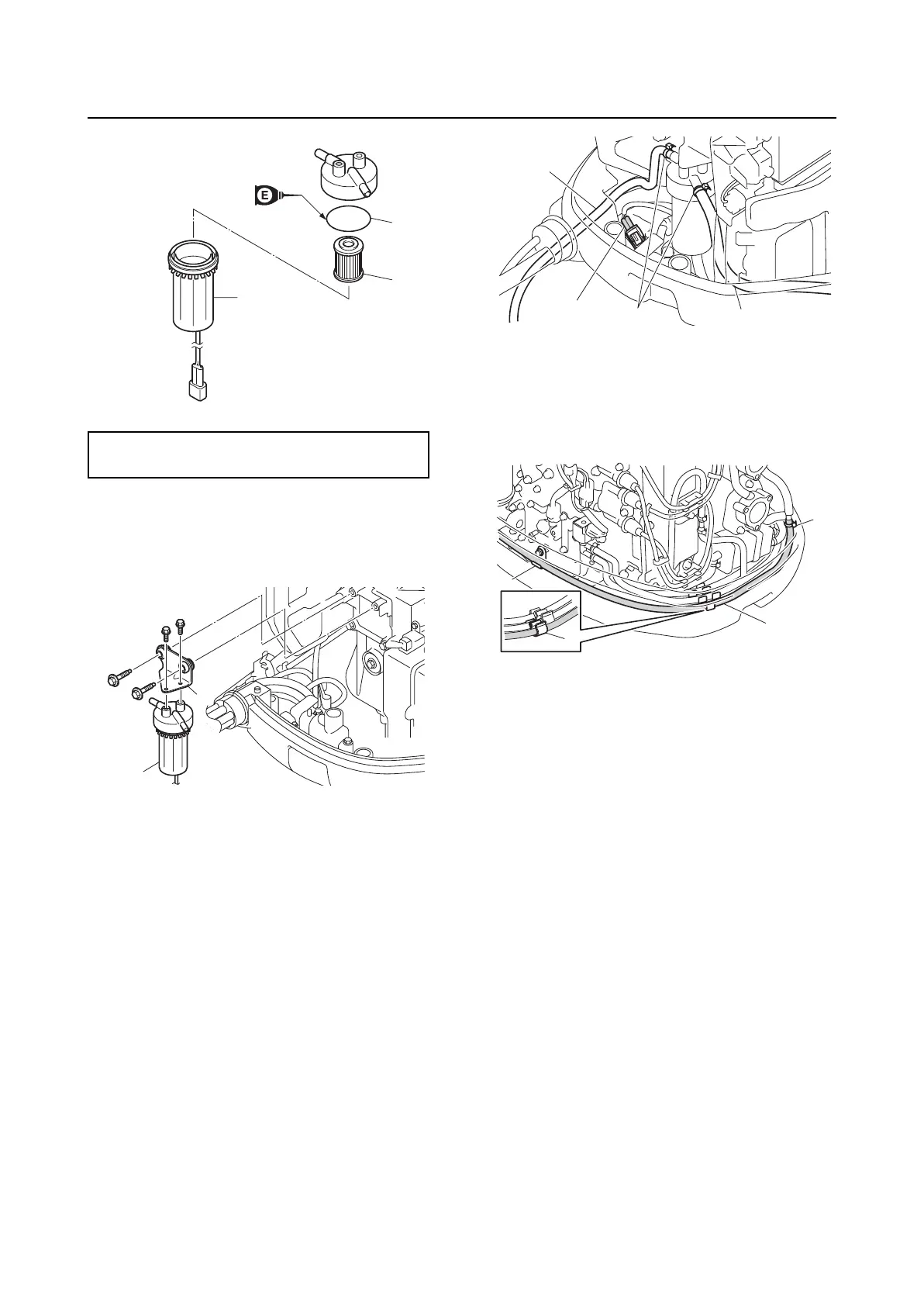
Fuel filter
0
1
2
3
4
5
6
7
8
9
10
A
Installing the fuel filter assembly
1. Install the bracket “1”.
2. Install the fuel filter assembly “2”.
3. Route the fuel hose “1” through the bot-
tom cowling.
4. Route the fuel hose “2” through the
proper holes in the rigging grommet. See
“Rigging grommet mounting” (3-9).
5. Install the retaining plate. See steps 4–6
in “Installing the rigging grommet” (3-13).
6. Connect the fuel hoses “1” and “2”, and
then fasten them using the plastic ties
“3”.
7. Connect the water detection switch cou-
pler “a”.
8. Install the fuel hose “1” to the holders “2”
and “3”.
9. Connect the fuel hose “1”, and then fas-
ten it using the plastic tie “4”.
Fuel cup assembly “3”:
5 N·m (0.5 kgf·m, 3.7 ft·lb)
3
1
2
1
2
2
a
3
1
1
4
3
2