9-32
Clamp bracket and swivel bracket
0
1
2
3
4
5
6
7
8
9
10
A
11. Inject grease into the grease nipples until
grease comes out from the bushings “a”.
12. Install the PTT unit. See “Installing the
PTT unit” (9-39).
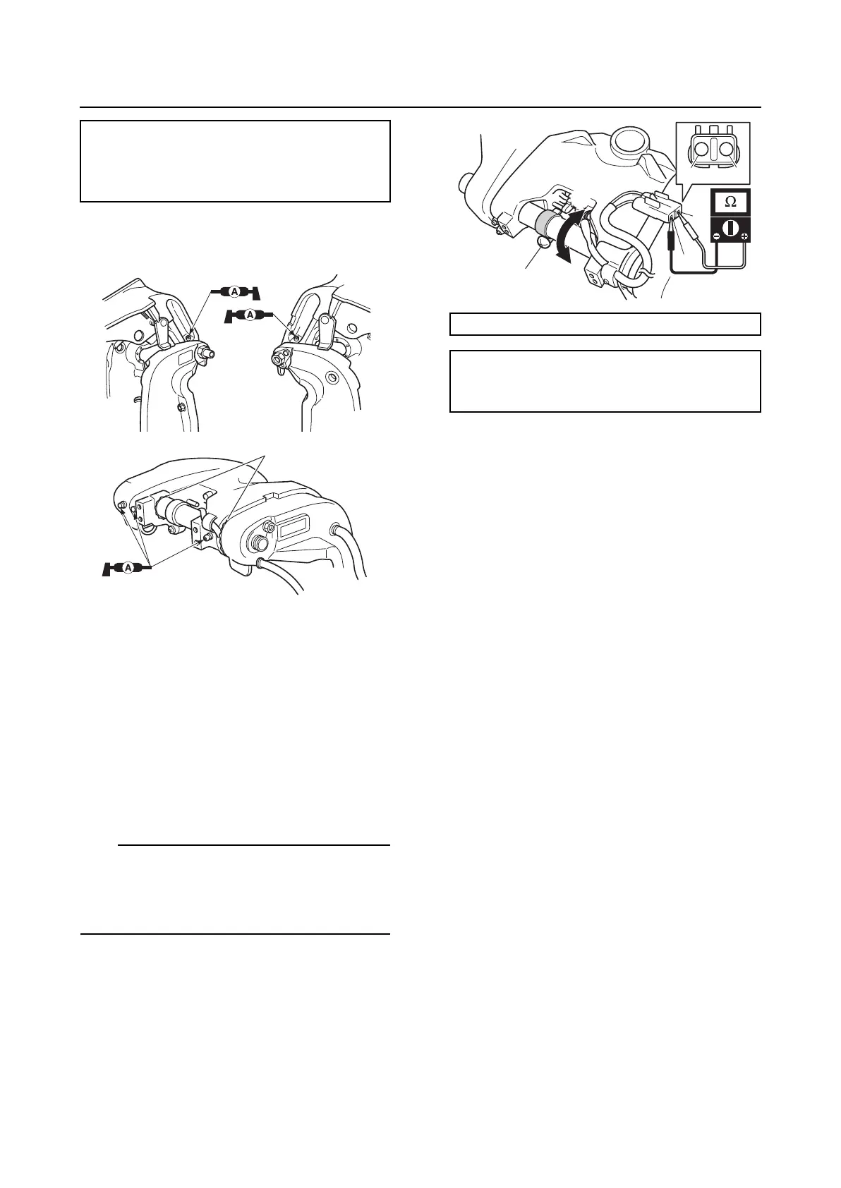
Adjusting the trim sensor cam
1. Fully tilt the swivel bracket down.
2. Loosen the trim sensor cam screw “1”.
3. Measure the trim sensor setting resis-
tance. Adjust if out of specification.
TIP:
• To decrease the resistance, turn the trim
sensor cam in direction “a”.
• To increase the resistance, turn the trim
sensor cam in direction “b”.
4. Tighten the trim sensor cam screw.
5. Check that the trim sensor setting resis-
tance is within specification.
Self-locking nut “3”:
15 N·m (1.5 kgf·m, 11.1 ft·lb)
Grease nipple “9”:
3 N·m (0.3 kgf·m, 2.2 ft·lb)
a
Digital circuit tester: 90890-03189
Trim sensor setting resistance:
Terminal “c”–Terminal “d”
9.0–11.0 Ω
1
c
c
d
d
a
b