9-31
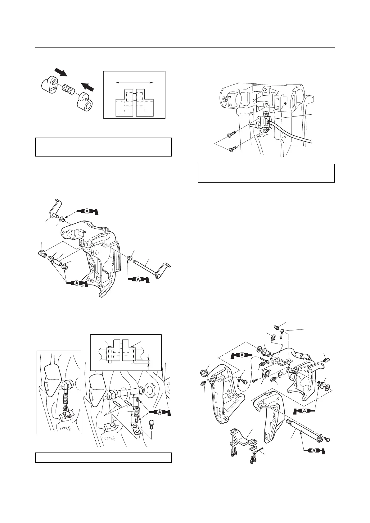
Clamp bracket and swivel bracket
2. Install the bushings “1” and “2”, collar “3”,
distance collar assembly “4”, and tilt stop
levers “5” and “6”.
3. Install the pins “1”, hook “2”, and spring
“3”.
4. Install the trim sensor “1”, and then
tighten the trim sensor screw “2” to the
specified torque.
5. Install the bushing “1”, through tube “2”
and temporarily tighten the self-locking
nut “3”.
6. Install the anode “4” and ground lead “5”.
7. Tighten the self-locking nut “3” to the
specified torque.
8. Install the ground leads “6” and “7”.
9. Install the trim sensor cam “8”.
10. Install the grease nipples “9”, and then
tighten them to the specified torque.
Distance “a”:
30.3–30.6 mm (1.19–1.20 in)
Distance “a”: 3.0 mm (0.12 in)
a
2
2
1
1
3
4
5
6
11
1
2
3
a
Trim sensor screw “2”:
4 N·m (0.4 kgf·m, 3.0 ft·lb)
1
2
7
2
3
4
6
5
9
9
9
9
9
1
1
8
9