6-40
Intake manifold and vapor separator
0
1
2
3
4
5
6
7
8
9
10
A
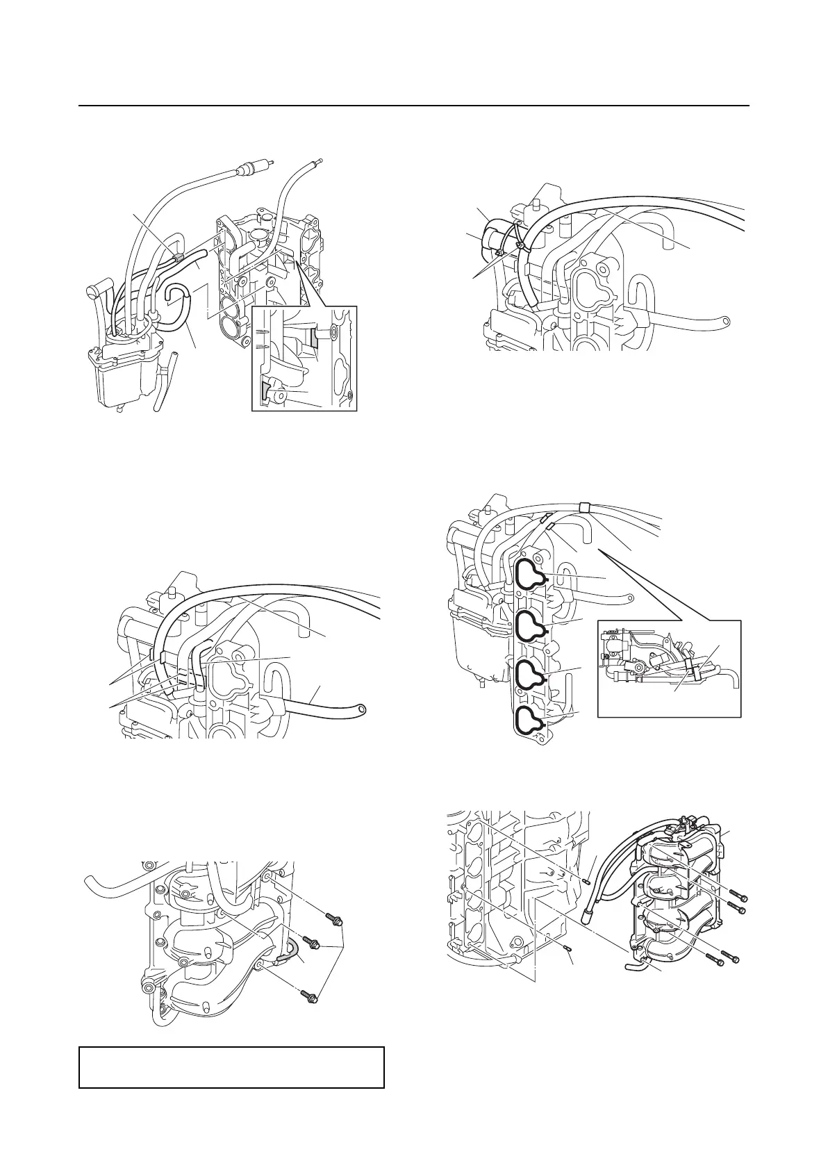
13. Route the fuel hose “2” through the gap
“c” in the intake manifold.
14. Fit the fuel hose “1” into the groove “a” in
the intake manifold.
15. Fit the vapor gas hose with filter “2” into
the groove “b” in the intake manifold.
16. Connect the pressure regulator hose “3”.
17. Tighten the vapor separator bolts “1” to
the specified torque.
18. Install the drain hose “2” to the intake
manifold.
19. Fasten the fuel filter “1”, vapor gas hose
with filter “2”, and air hose “3” using the
plastic ties “4”.
Installing the intake manifold
1. Install new gaskets “1” onto the intake
manifold.
2. Install the holders “2” and “3” to the vapor
gas hoses.
3. Install the dowels “1” and intake manifold
“2”.
4. Install the vaper gas hose “1” to the
holder “2”.
Vapor separator bolt “1”:
5 N·m (0.5 kgf·m, 3.7 ft·lb)
2
b
c
1
a
b
1
3
2
a
1
2
4
3
1
2
2
2
1
3
3
1
1
1
1
2
1