9-60
PTT gear pump
0
1
2
3
4
5
6
7
8
9
10
A
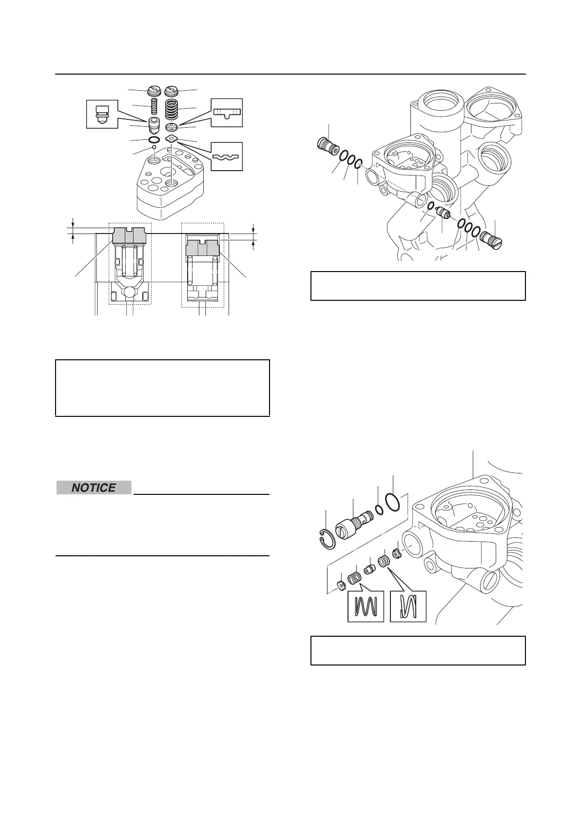
A. Up-relief valve
B. Down-relief valve
Assembling the gear pump housing
Lubricate the parts using ATF Dexron II dur-
ing assembly.
When assembling the PTT unit, do not use
a rag. Otherwise, dust and particles could
get on the PTT unit components, causing
poor performance.
1. Install new O-rings “1”, “2”, and “3” to the
main valves “4”.
2. Install a new O-ring “5” to the shuttle pis-
ton “6”.
3. Install the shuttle piston “6” and main
valves “4”, and then tighten the main
valves “4” to the specified torque.
4. Install the manual valve seat “1”, spring
“2”, adapter “3”, spring “4”, and manual
valve seat “5”.
5. Install a new O-ring “6” to the manual
valve “7”, and then install a new O-ring
“8”, manual valve “7”, and circlip “9”.
6. Tighten the manual valve “7” to the spec-
ified torque.
7. Install the ball “1” and plug “2”, and then
tighten the plug “2” to the specified
torque.
Installation height “a” (reference data):
1.63–1.83 mm (0.064–0.072 in)
Installation depth “b” (reference data):
1.77–2.27 mm (0.070–0.089 in)
AB
9
4
a
b
49
8
6
5
7
3
2
1
Main valve “4”:
11 N·m (1.1 kgf·m, 8.1 ft·lb)
Manual valve “7”:
3 N·m (0.3 kgf·m, 2.2 ft·lb)
1
1
2
2
3
3
4
4
5
6
9
7
6
8
5
4
3
2
1