5-43
PTT system
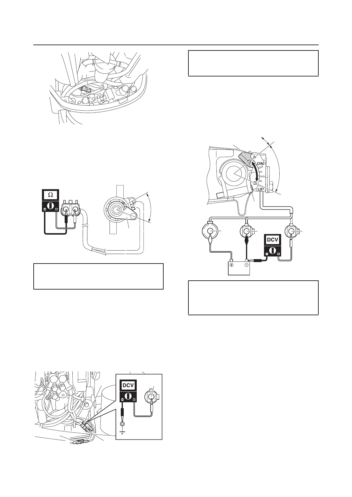
2. Measure the trim sensor resistance.
3. Turn the trim sensor lever “1” from the
position “a” to the position “b”, and then
measure the resistance as it gradually
changes.
4. Connect the trim sensor coupler.
Checking the tilt limiter (optional)
1. Disconnect the tilt limiter couplers “a”,
“b”, and “c”.
2. Measure the input voltage at the tilt lim-
iter coupler “a” with the up side of the
PTT switch pushed.
3. Connect the battery leads to the tilt lim-
iter couplers.
4. Loosen the screw “1”, and then measure
the output voltage when sliding the mag-
net “2” against the tilt limiter.
5. Connect the tilt limiter couplers.
6. Set the tilt limiter. See “Setting the tilt lim-
iter” (3-18).
Trim sensor resistance (reference data):
239–379 Ω at “a”
9.0–11.0 Ω at “b” (setting resistance)
a
1
a
b
Sb
a
b
c
Tilt limiter input voltage:
Sky blue (Sb)–Ground
12 V (battery voltage)
Tilt limiter output voltage:
Blue (L)–Ground
12.0 V (battery voltage) at “a”
0V at “b”
LB
Sb
a
b
2
1