8-39
Shimming (regular rotation model)
Selecting the pinion shim (T3)
• Spray anti-rust lubricant on the bearing
before installation. Do not apply gear oil to
the parts. Otherwise, correct measure-
ments cannot be obtained.
• Keep the parts free of foreign material,
such as dirt and lint.
Be careful not to damage the measure-
ment plane surface of the special service
tool. Otherwise, correct measurements
cannot be obtained.
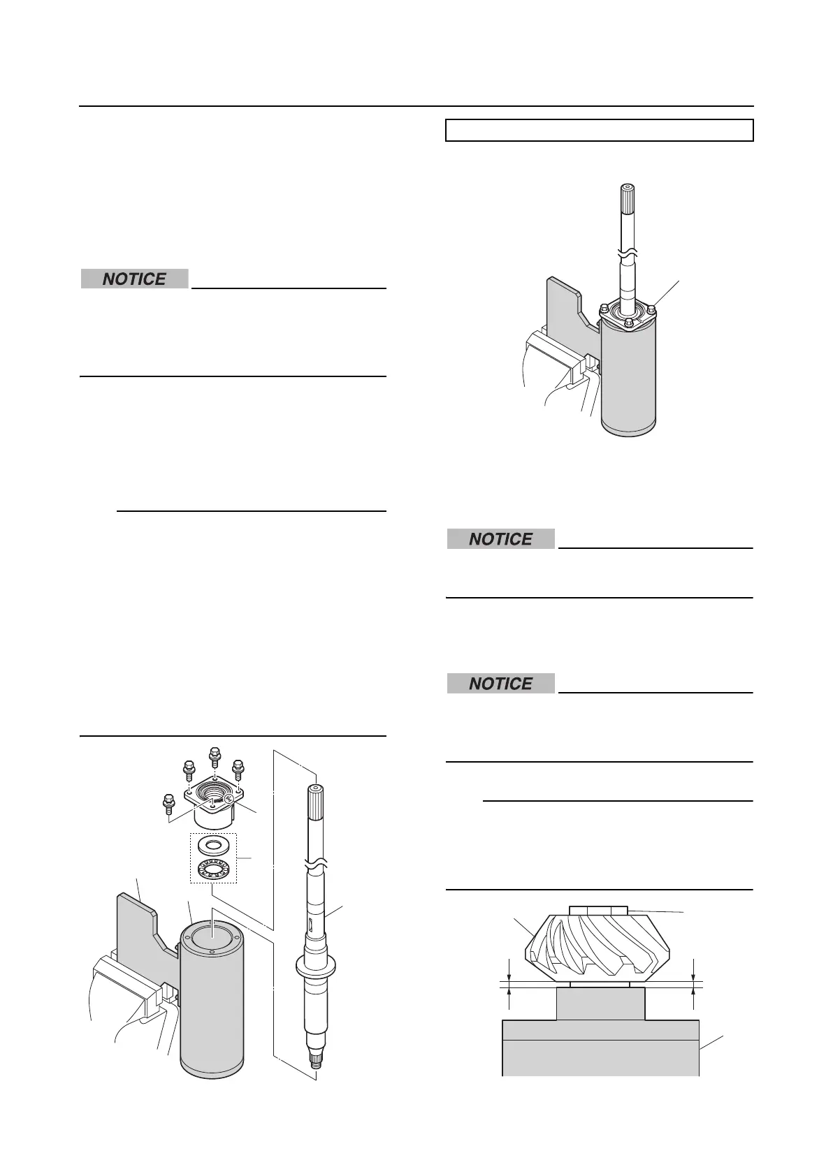
1. Hold the special service tool “1”, and
then install the drive shaft “2”, thrust
bearing “3”, and drive shaft housing
assembly to the special service tool.
TIP:
• Do not install the pinion shims (T3) and
O-ring. Make sure that the pinion shims
(T3) are not affixed to the thrust bearing
outer race.
• Make sure to install the thrust bearing outer
race so that it is facing the same direction
as when it was removed.
• Make sure that the cutout “a” in the drive
shaft housing assembly is facing the oppo-
site direction of the plate “4” of the special
service tool.
2. Tighten the drive shaft housing bolts “1”.
3. Install the pinion “1” and pinion nut “2”,
and then tighten the pinion nut “2”
temporarily.
When tightening the pinion nut, check
that the drive shaft turns smoothly.
4. Check that there is a gap “a” between the
pinion “1” and the special service tool “3”.
If there is no gap and the drive shaft does
not turn, the special service tool could be
damaged.
TIP:
If there is no gap, the thrust bearing outer
race “4” may not have been installed. If the
gap is 1.0 mm (0.039 in) or more, the pinion
shims (T3) “5” may not have been removed.
1
2
3
a
4
Pinion height gauge “1”: 90890-06671
1
1
2
3
aa