8-40
Shimming (regular rotation model)
0
1
2
3
4
5
6
7
8
9
10
A
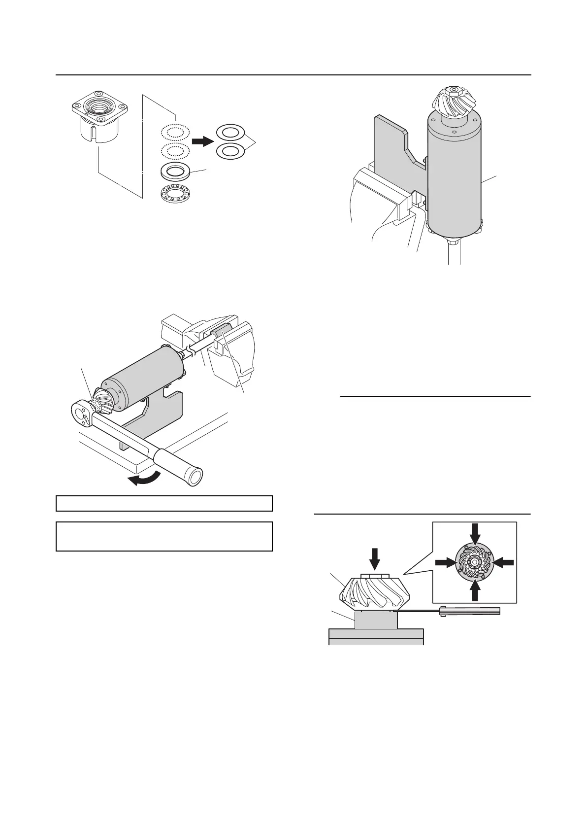
5. Install the special service tool “1” to the
drive shaft spline and hold the special
service tool “1”.
6. Tighten the pinion nut “2” to the specified
torque.
7. Hold the special service tool “1” so that
the pinion is facing up.
8. Turn the drive shaft 10 turns or more to
seat the thrust bearing.
9. Push down on the pinion “1” so that it
does not lift up, and then measure the
distance between the pinion “1” and the
special service tool “2”.
TIP:
• When measuring the distance, insert the
end of the thickness gauge straight into the
gap at the measurement point. Do not
insert the thickness gauge at an angle.
• Measure the distance at 4 points: “a”, “b”,
“c”, and “d”.
• Write down the measurement data in the
shimming check sheet.
10. Determine the distance average, and
then round down the average to 2
decimal places.
Drive shaft holder 6 “1”: 90890-06520
Pinion nut “2”:
95 N·m (9.5 kgf·m, 70.1 ft·lb)
4
5
1
2
1
1
2
a
b
c
d