5-27
Starting unit and component
6. Install the shift position switch. See “Shift
rod and shift bracket” (9-1).
7. Connect the shift position switch coupler.
Checking the engine shut-off switch
1. Disconnect the 10-pin coupler or engine
start switch coupler.
2. Turn the engine start switch to ON, and
then check the engine shut-off switch for
continuity.
1. OFF
2. ON
3. START
A. 704 remote control
B. 703 remote control
3. Turn the engine start switch to OFF.
4. Connect the 10-pin coupler or engine
start switch coupler.
Starting unit and component
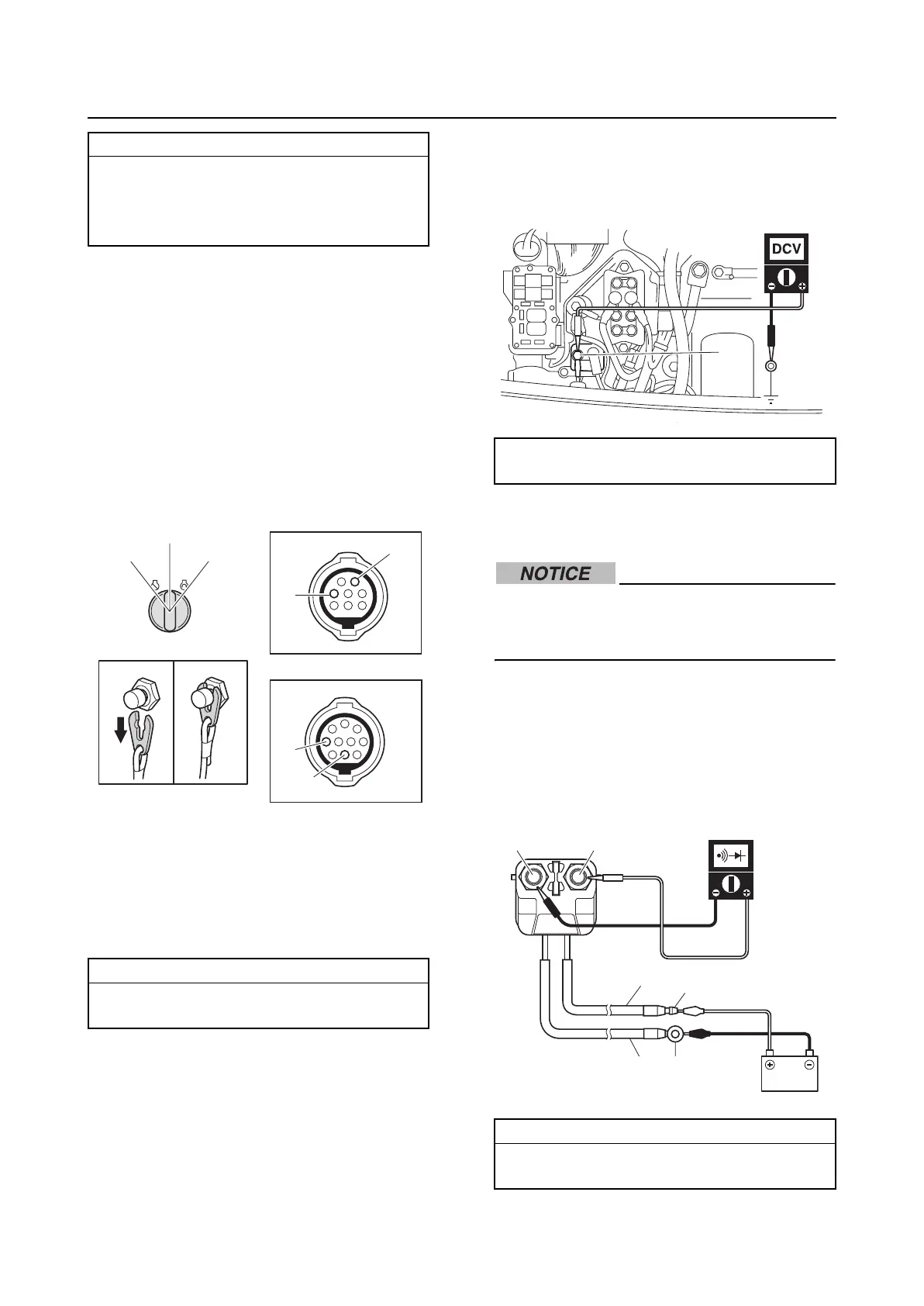
Checking the starter relay
1. Measure the input voltage between the
starter relay terminal “a” and ground.
2. Disconnect the starter relay leads, and
then remove the starter relay.
Before disconnecting the starter relay ter-
minals, make sure to disconnect the neg-
ative battery terminal.
3. Connect the positive battery lead to the
relay connector “a”, and the negative bat-
tery lead to the relay lead “b”, and then
check for continuity between terminals
“c” and “d”. Replace the starter relay if
out of specification.
Shift position switch continuity:
Continuity:
Switch position “a”
No continuity:
Switch position “b”
Engine shut-off switch continuity:
Clip removed:
Terminal “a”–Terminal “b”
B
A
a
a
b
b
3. START
2. ON
1. OFF
Terminal “a”–Ground:
12 V (battery voltage)
Relay terminals continuity:
Battery lead connected:
Terminal “c”–Terminal “d”
a
B
Br
c
a
b
d