5-19
Charging unit and component
5. Check that the vapor shut-off valve
opens and the negative pressure is
released when the battery leads are
connected to the vapor shut-off valve
terminals.
Connect the battery leads to the vapor
shut-off valve terminals for only a few sec-
onds.
6. Remove the special service tool.
7. Measure the resistance between the
vapor shut-off valve terminals.
8. Install the vapor shut-off valve, and then
connect the vapor shut-off valve coupler.
Charging unit and component
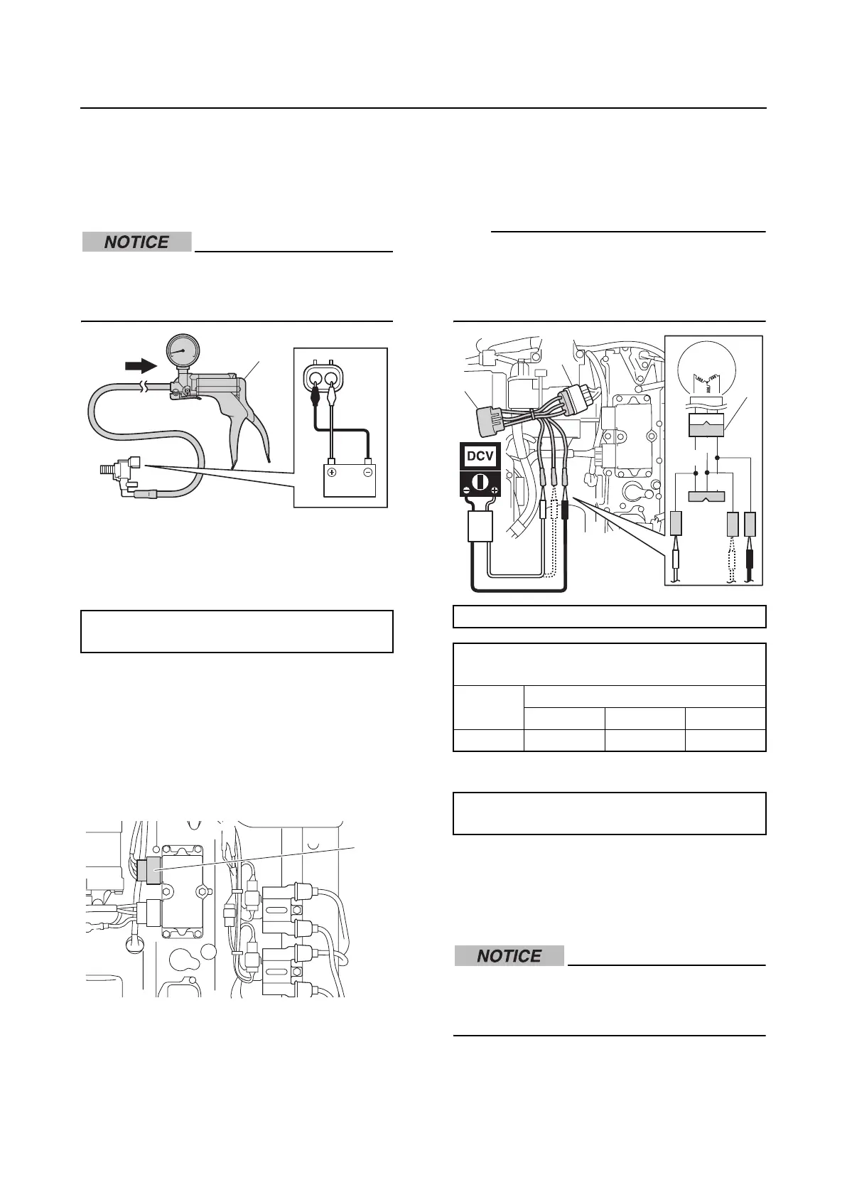
Checking the lighting coil (stator
assembly)
1. Disconnect the lighting coil coupler “a”.
2. Connect the special service tool “1”.
3. Measure the lighting coil output peak
voltage between all combinations of the
connectors. Replace the stator assembly
if below specification.
TIP:
When measuring the lighting coil output peak
voltage under the cranking (unloaded) condi-
tion, remove the clip from the engine shut-off
switch to prevent the engine from starting.
4. Measure the lighting coil resistance.
5. Disconnect the special service tool, and
then connect the lighting coil coupler.
Checking the Rectifier Regulator
Do not connect the battery cables in
reverse. Otherwise, the Rectifier Regula-
tor could be damaged.
1. Disconnect the Rectifier Regulator cou-
pler “a”.
Vapor shut-off valve resistance:
30.0–34.0 Ω at 20 °C (68 °F)
1
a
Test harness (3 pins) “1”: 90890-06847
Lighting coil output peak voltage:
Green (G)–Green (G)
r/min
Unloaded
Cranking 1500 3500
DC V 11.0 50.0 110.0
Lighting coil resistance (reference data):
0.2–0.3 Ω at 20 °C (68 °F)
G
G
G
1
1
a